
Thermal management composite heat shield

a heat shield and composite technology, applied in the field of thermal management, can solve the problems of less heat tolerant, large heat generation of mechanical and/or electrical systems, and component temperature exceeding 1000 degrees fahrenheit, and achieve the effect of reducing the porosity of the assembly

Inactive Publication Date: 2010-08-05
THE BF GOODRICH CO
View PDF23 Cites 37 Cited by
  • Summary
  • Abstract
  • Description
  • Claims
  • Application Information

AI Technical Summary

Benefits of technology

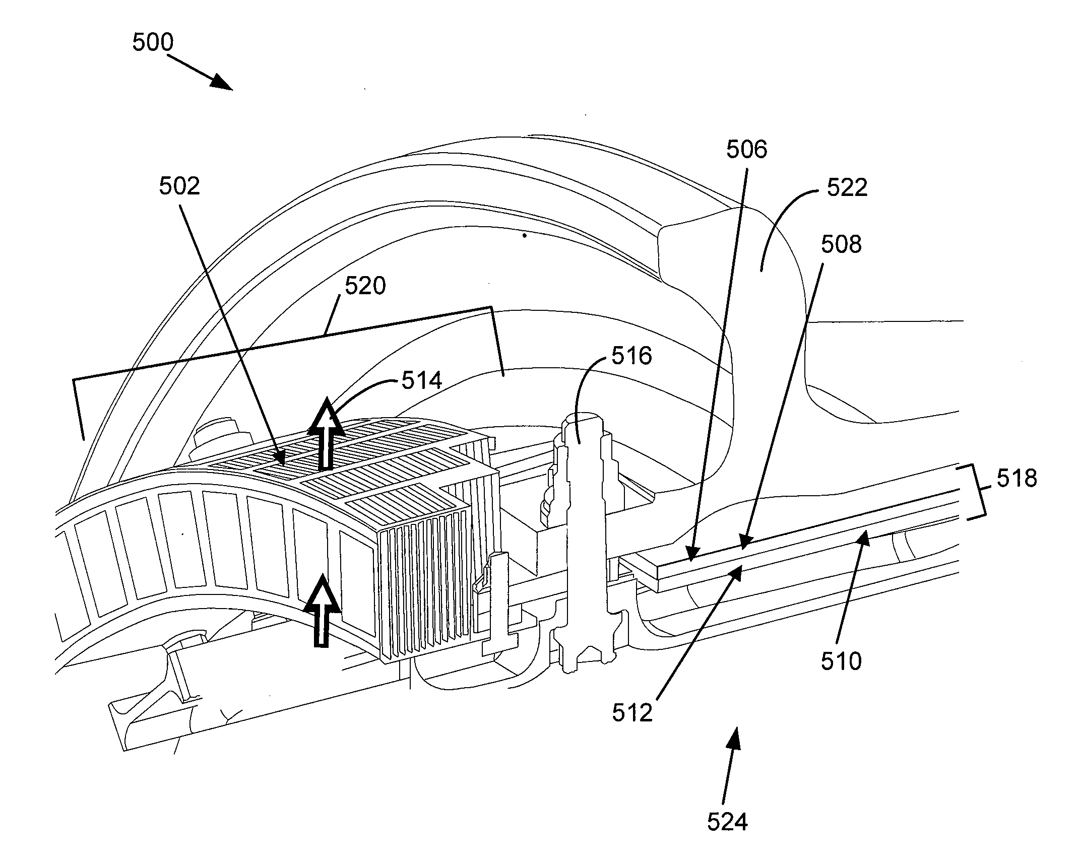
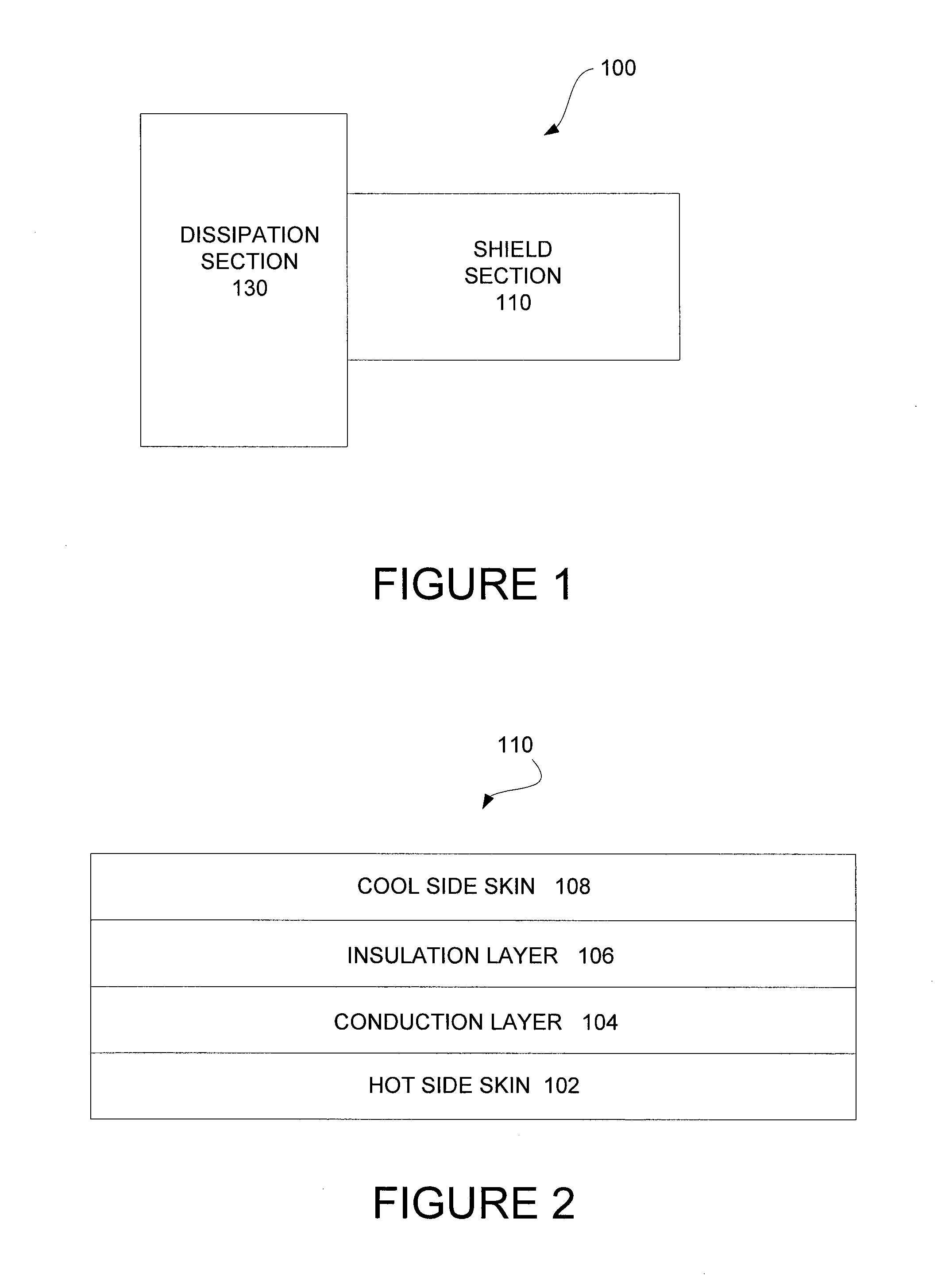
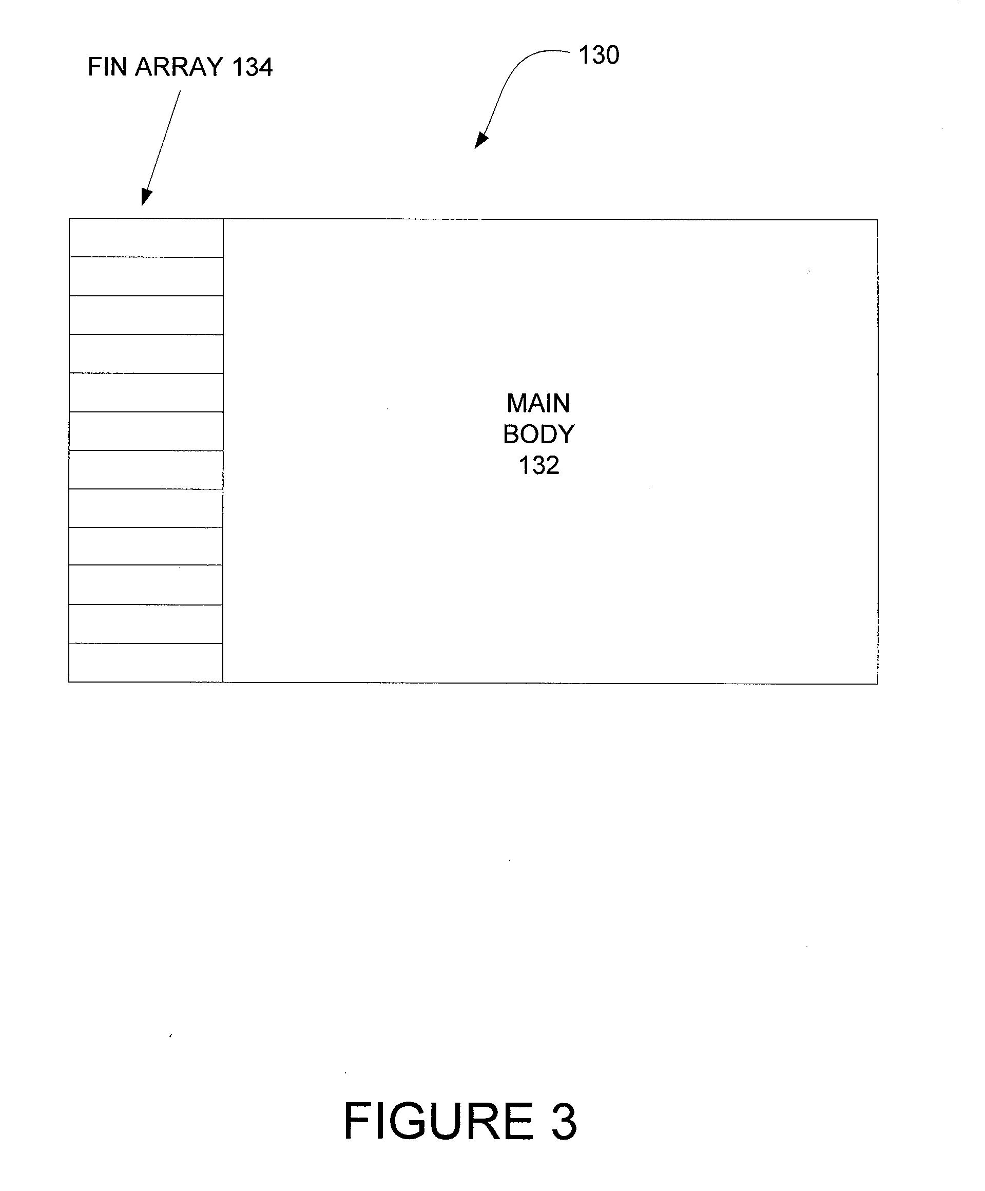
[0008]In various embodiments, the shield portion comprises a hot side skin, a conduction layer, an insulation layer, and a cool side skin, while the dissipation portion may comprise a fin array and an optional main body (which may itself by incorporated into the fin array). The conduction layer may comprise a planar carbon fiber structure or graphite flake configured with an in-plane thermal conductivity from about 100 watts per meter-Kelvin to greater than about 2000 watts per meter-Kelvin. The insulation layer may comprise a planar nanoporous structure configured with a through-plane thermal conductivity of less than about 25 watts per mete

Problems solved by technology

Various mechanical and / or electrical systems, such as braking systems (and in particular, aircraft braking systems), typically generate significant heat.
For example, an aircraft brake pad friction component may absorb a significant amount of heat during braking (e.g., resulting in a brake pad friction component temperature exceeding 1000 degrees Fahrenheit), while other components in the vicinity of the brakes, such as an aluminum wheel, may be less heat tolerant.
However, bringing the cooling medium to the heat source is often not practical and / or may be expensive.

Method used


Image

  • Thermal management composite heat shield
  • Thermal management composite heat shield
  • Thermal management composite heat shield

Examples


Embodiment Construction

[0017]The detailed description of exemplary embodiments herein makes reference to the accompanying drawings, which show exemplary embodiments by way of illustration and its best mode. While these exemplary embodiments are described in sufficient detail to enable those skilled in the art to practice the invention, it should be understood that other embodiments may be realized and that logical, chemical and mechanical changes may be made without departing from the spirit and scope of the invention. Thus, the detailed description herein is presented for purposes of illustration only and not of limitation. For example, the steps recited in any of the method or process descriptions may be executed in any order and are not necessarily limited to the order presented. Moreover, many of the functions or steps may be outsourced to or performed by one or more third parties. Furthermore, any reference to singular includes plural embodiments, and any reference to more than one component or step ...


PUM

PropertyMeasurementUnit
Temperatureaaaaaaaaaa
Densityaaaaaaaaaa

Abstract

A thermal management system and methods for use are disclosed. The thermal management system comprises a shield portion and a dissipation portion. The shield portion may comprise a hot side skin, a conduction layer, an insulation layer, and a cool side skin. The dissipation portion may comprise a fin array. Heat absorbed by the shield portion is partially or fully conducted to the dissipation portion for transfer to the ambient environment. The thermal management system may be employed as an aircraft wheel heat shield, an automotive brake heat shield, a gas turbine heat shield, an electronic heat sink, and in various other applications where heat shielding and / or heat transfer are desirable.

Description

CROSS REFERENCE TO RELATED APPLICATIONS[0001]This application claims priority to and the benefit of U.S. Provisional Application Ser. No. 61 / 149,178, filed on Feb. 2, 2009, entitled “THERMAL MANAGEMENT COMPOSITE HEAT SHIELD,” which is incorporated by reference herein.FIELD OF INVENTION[0002]The present invention generally relates to thermal management, and more particularly, to thermal transmission and thermal shielding in brake systems.BACKGROUND OF THE INVENTION[0003]Various mechanical and / or electrical systems, such as braking systems (and in particular, aircraft braking systems), typically generate significant heat. For example, significant heat is generated when the kinetic energy of a vehicle is converted to thermal energy. To help compensate for the increased temperatures, individual brake components (e.g., brake pads, rotors, and the like) may be configured to tolerate high temperatures.[0004]For example, an aircraft brake pad friction component may absorb a significant amou...

Claims


Application Information

Patent Timeline
IPC IPC(8): B60B19/10F28F7/00B23P11/00
CPCB60T5/00B64C25/42F16D2065/785B32B5/024Y10T29/49826B32B5/26B32B2307/30B32B2307/306B32B2605/18F16D65/847F23R3/283H01L23/3731H01L23/3735H01L23/3737H01L23/467H05K7/2039
Inventor WALTZ, JAMES C.
Owner THE BF GOODRICH CO
Learn More