

Power Supply System Provided With a Plurality of Power Supplies, and Vehicle Provided With Such Power Supply System
- Summary
- Abstract
- Description
- Claims
- Application Information
AI Technical Summary
Benefits of technology
Problems solved by technology
Method used
Image

Examples
example modification
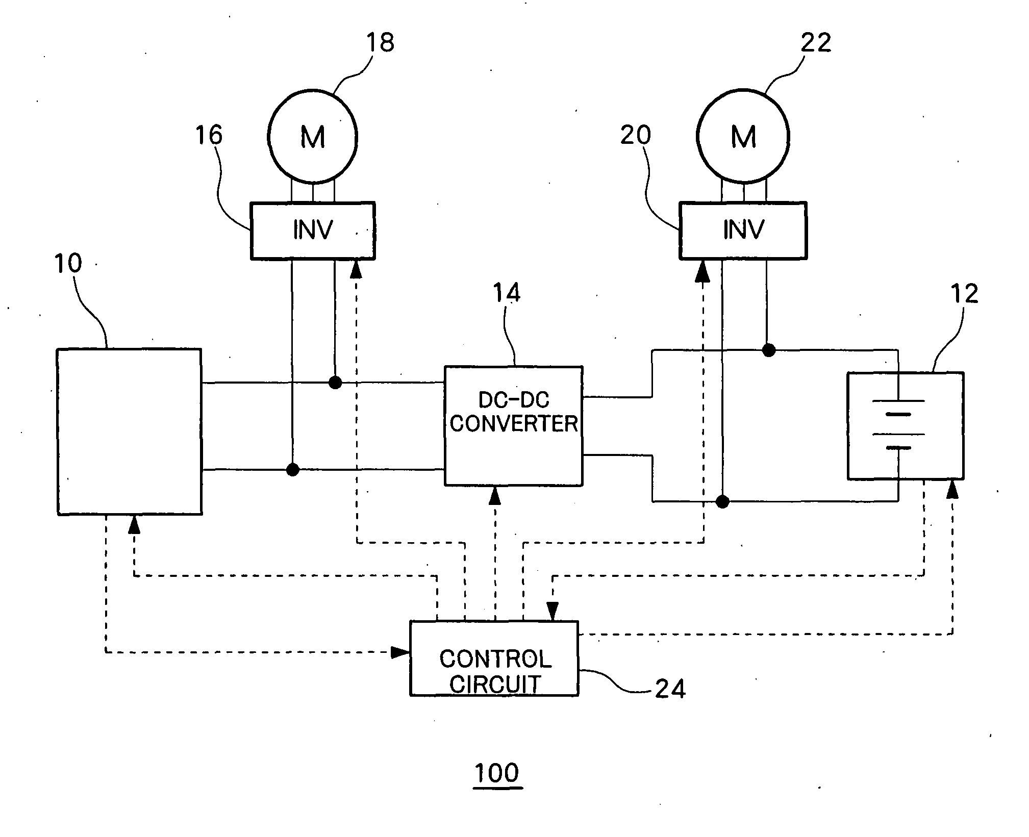
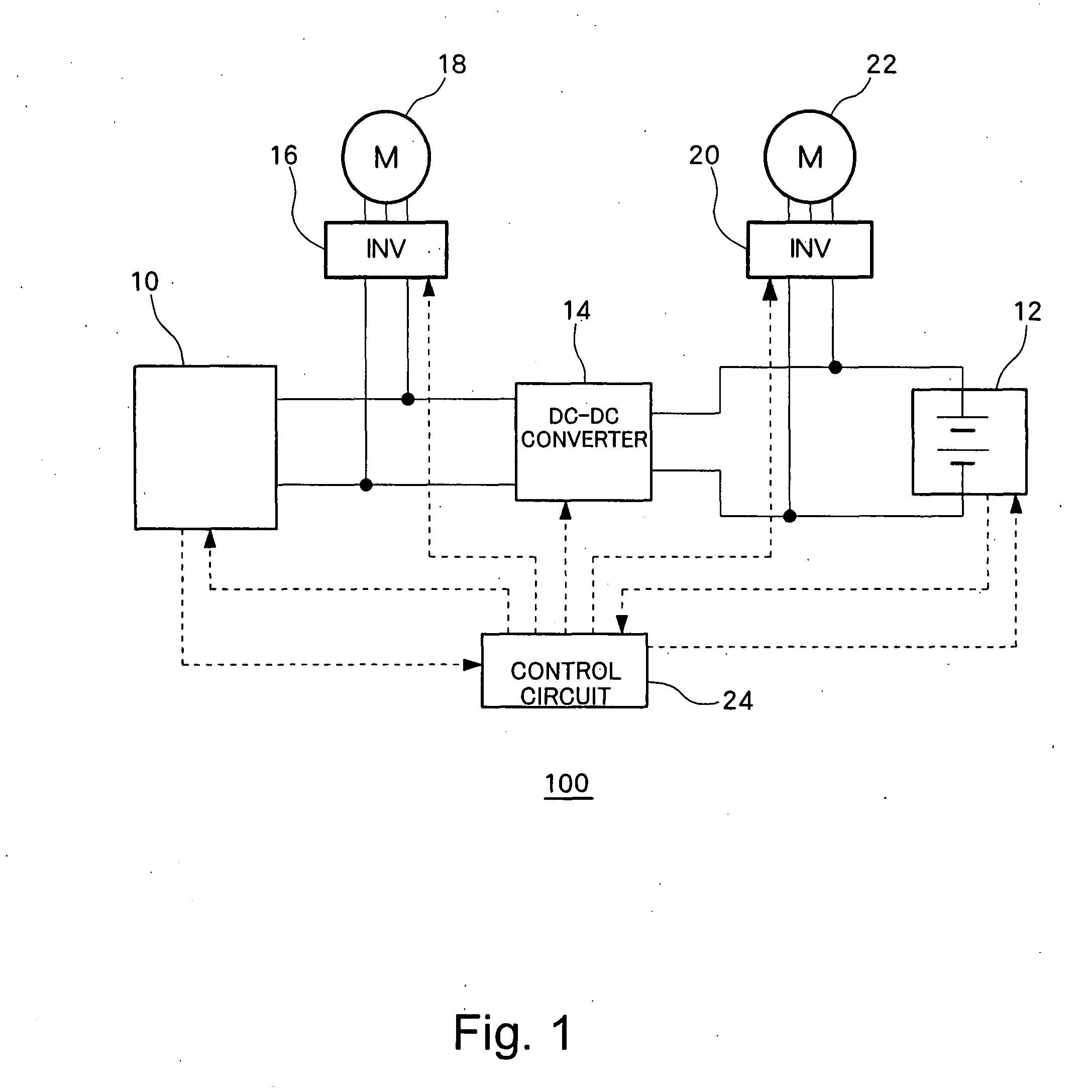
[0061]The present invention can be applied to an electric power system and a vehicle having two or more electric power supplies. For example, as shown in FIG. 6, the present invention can be applied to an electric power system 102 in which three electric power supplies 10, 12, 26 are connected each other via two voltage converters 14, 28.
[0062]Here, the third electric power supply 26 is a DC power supply which is used as an auxiliary power supply of the electric power system 102. Often, the third electric power supply 26 is an electric power supply having different output voltage from the output voltage of the first electric power supply 10. The third electric power supply 26 is preferably a secondary cell which can charge and discharge regenerated energy from a motor and an excessive electric power from the first electric power supply 10. The third electric power supply 26 is configured in such a manner that the output power is controllable according to a control signal from the co...
PUM
 Abstract
Description
Claims
Application Information