Surface light source apparatus

Active Publication Date: 2010-08-05
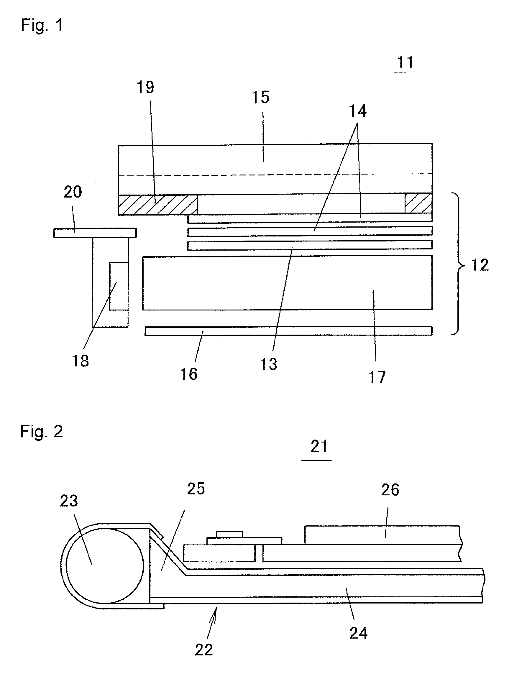
TOHOKU DENSHI CO LTD
View PDF6 Cites 37 Cited by
  • Summary
  • Abstract
  • Description
  • Claims
  • Application Information

AI Technical Summary

Benefits of technology

[0060]In view of the above technical problems, it is an object of the present invention to provide a surface light source apparatus in which a thickness of an end face of a light introducing section is substantially equal to a height of a light outputting window

Problems solved by technology

However, if the thickness of the light guide plate is made smaller than the height of the light outputting window of the point light source, the light that does not enter the light guide plate of the light emitted from the point light source increases and the light usage efficiency of the surface light source apparatus lowers.
Thus, the thickness of the light guide plate is subjected to restriction by the height of the light outputting window of the point light source, and it is difficult to have the thickness of the surface light source apparatus smaller than the height of the light outputting window of the point light source.
Similarly, if the light source is a cold cathode tube, it is difficult to have the thickness of the light guide plate smaller than the diameter of the cold cathode tube.
However, in

Method used


Image

  • Surface light source apparatus
  • Surface light source apparatus
  • Surface light source apparatus

Examples


first embodiment

[0235]First embodiment of the present invention will be described. FIG. 23 is a perspective view showing a surface light source apparatus 61 according to a first embodiment of the present invention, and FIG. 24 is a schematic cross-sectional view thereof. The surface light source apparatus 61 includes a point light source 62 and a light guide plate 63. The point light source 62 incorporates one or a plurality of LEDs, and emits white light. An LED 62b is sealed in a transparent sealing resin 62c, and the transparent sealing resin 62c is covered by a white resin 62d excluding a front surface, where the front surface exposed from the white resin 62d of the transparent sealing resin 62c is a light outputting window 62a. The point light source 62 is small compared to the width of the light guide plate 63 (dimension in a depth direction in the plane of FIG. 24), and thus is referred to as a point light source as opposed to a cold cathode tube being referred to as a linear light source.

[0...

second embodiment

[0277]FIG. 38 is a perspective view showing a surface light source apparatus 71 according to a second embodiment of the present invention. In the surface light source apparatus 71, the envelope curves on the upper end side and the lower end side of the directivity converting pattern 68 respectively have a linear shape. In other words, the light introducing section 65 is formed over the entire width of the end of the light guide plate 63, and the directivity converting pattern 68 is formed over the entire inclined surface of a plane shape of the light introducing section 65. However, the V-shaped groove structure 68a arranged in the directivity converting pattern 68 is arranged to radially extend with the point light source 62 as the center when seen from a direction perpendicular to the light outputting surface 69. FIG. 39(a) shows a shape of the V-shaped groove structure 68a of the left end portion of the directivity converting pattern 68, FIG. 39(b) shows a shape of the V-shaped g...

third embodiment

[0282]FIG. 42 is a perspective view showing a surface light source apparatus 81 according to a third embodiment of the present invention. The surface light source apparatus 81 includes a plurality of point light sources 62, and a plurality of light introducing sections 65 is arranged facing each point light source 62. The adjacent directivity converting patterns 68 may interfere with each other if the plurality of light introducing sections 65 is arranged, and thus the light introducing sections 65 are preferably arranged at an inter-center pitch of about 5 to 10 mm. In such an embodiment, the surface light source apparatus 81 can be made brighter since a plurality of point light sources 62 is used.

[0283]FIG. 43(a) is an explanatory view describing a variant of the surface light source apparatus according to the third embodiment, and FIG. 43(b) is an enlarged view of a portion surrounded with a circle of FIG. 43(a). In this variant, the arrangement pitch of the point light sources 6...


PUM


Abstract

A light guide plate (63) includes a light introducing section (65), which is at a position facing a point light source (62), for confining light from the point light source, and a light guide plate main body (64), which has a thickness smaller than a thickness at an end of the light introducing section on the point light source side, for outputting the confined light to an outside from a light outputting surface by light outputting means (70). The light introducing section (65) has an inclined surface (67), which is inclined from a surface of the light introducing section towards a surface of the light guide plate main body (64). The inclined surface (67) has a directivity converting pattern (68) for converting a directivity expansion in a thickness direction of the light guide plate of the light entered to the light introducing section (65) to directivity characteristics tilted towards a direction parallel to a surface direction of the light guide plate. The directivity converting pattern (68) has a structure in which a plurality of V-shaped groove structures (68a) are lined.

Description

TECHNICAL FIELD[0001]The present invention relates to a surface light source apparatus and a liquid crystal display device, and in particular, to a structure of a surface light source apparatus for efficiently entering light to a light guide plate having a thickness smaller than a thickness of a light source.BACKGROUND ART[0002]FIG. 1 shows a schematic view of a conventional liquid crystal display device using an edge light surface light source apparatus. A liquid crystal display device 11 is configured by a surface light source apparatus 12 and a liquid crystal panel 15.[0003]The surface light source apparatus 12 has a point light source 18 using an LED arranged facing an end face (light incident surface) of a light guide plate 17 molded by a transparent resin, a diffusion plate 13 and two prism sheets 14 stacked on an upper surface (light outputting surface) of the light guide plate 17, and a reflection plate 16 arranged facing a lower surface of the light guide plate 17. The poin...

Claims


Application Information

Patent Timeline
IPC IPC(8): G02F1/1335F21V7/04
CPCG02B6/0016G02B6/0018G02B6/0038G02B6/0036G02B6/0035G02B6/002G02B6/00G02F1/1335G02B6/0001
Inventor SHINOHARA, MASAYUKITANOUE, YASUHIROHIROTA, KAZUHIDETAKEMURA, KOICHIIWASE, TAKUMAISHIKAWA, TAKAKOUENO, YOSHIHIROOTA, MORIHISAKISHIMOTO, JUNKURATA, GOUOTAKAHASHI, YUKIHIROMIYAMOTO, HIROYUKI
Owner TOHOKU DENSHI CO LTD
Why Eureka
Try Eureka