Electrode structure of piezoelectric element, method of forming electrode of piezoelectric element, piezoelectric actuator, and head suspension

a piezoelectric element and electrode technology, applied in the field of head suspension, can solve the problems of increasing the risk of causing a short circuit between the electrodes of the piezoelectric elements and the attaching parts, uneven dispersion of filler in the adhesive, and the risk of contacting the piezoelectric elements with the attaching parts

Active Publication Date: 2010-08-05
NHK SPRING CO LTD
View PDF23 Cites 55 Cited by
  • Summary
  • Abstract
  • Description
  • Claims
  • Application Information

AI Technical Summary

Benefits of technology

[0016]This aspect of the present invention causes no short circuit between the electrode of the piezoele

Problems solved by technology

To effectively use a space, the piezoelectric elements are arranged in the opening close to the periphery of the opening, and therefore, the electrodes of the piezoelectric elements have a risk of contacting the attaching part.
The filler tends to unevenly disperse in the adhesive, to cause a short circuit between the electrodes of the piezoelec

Method used


Image

  • Electrode structure of piezoelectric element, method of forming electrode of piezoelectric element, piezoelectric actuator, and head suspension
  • Electrode structure of piezoelectric element, method of forming electrode of piezoelectric element, piezoelectric actuator, and head suspension
  • Electrode structure of piezoelectric element, method of forming electrode of piezoelectric element, piezoelectric actuator, and head suspension

Examples


Embodiment Construction

[0028]An electrode structure of a piezoelectric element, a method of forming an electrode of a piezoelectric element, a piezoelectric actuator, and a head suspension according to embodiments of the present invention will be explained.

[0029]First, a head suspension employing piezoelectric elements each with an electrode structure according to an embodiment of the present invention will be explained.

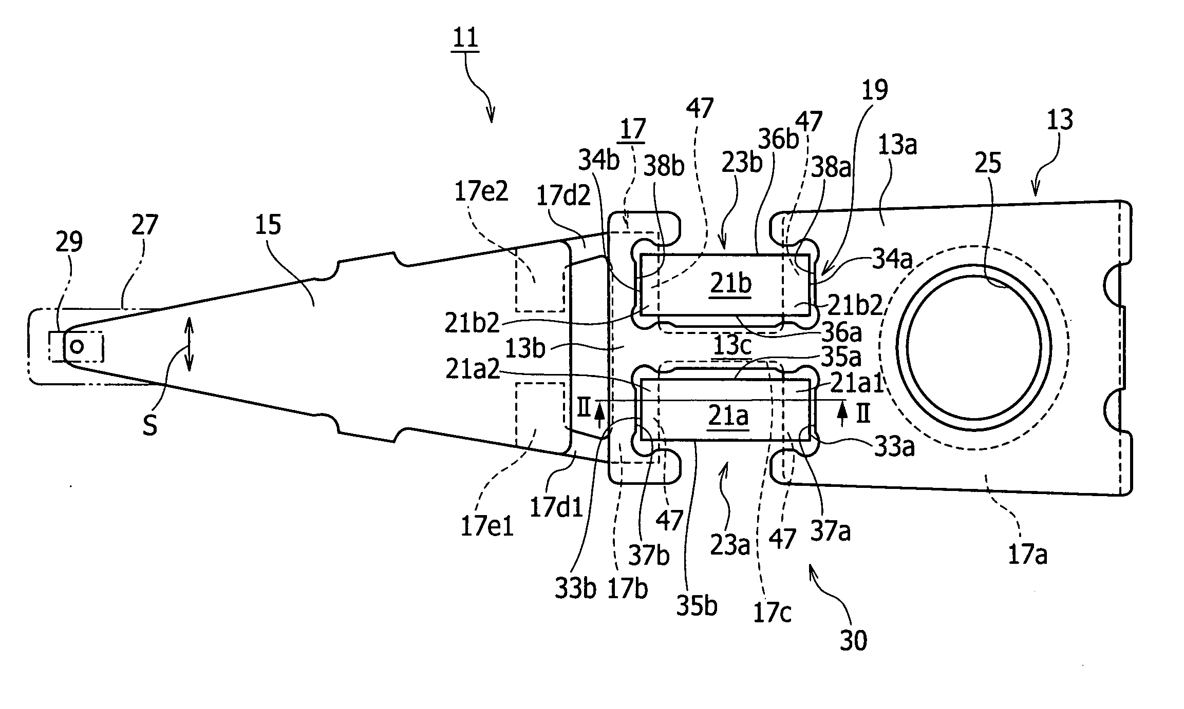
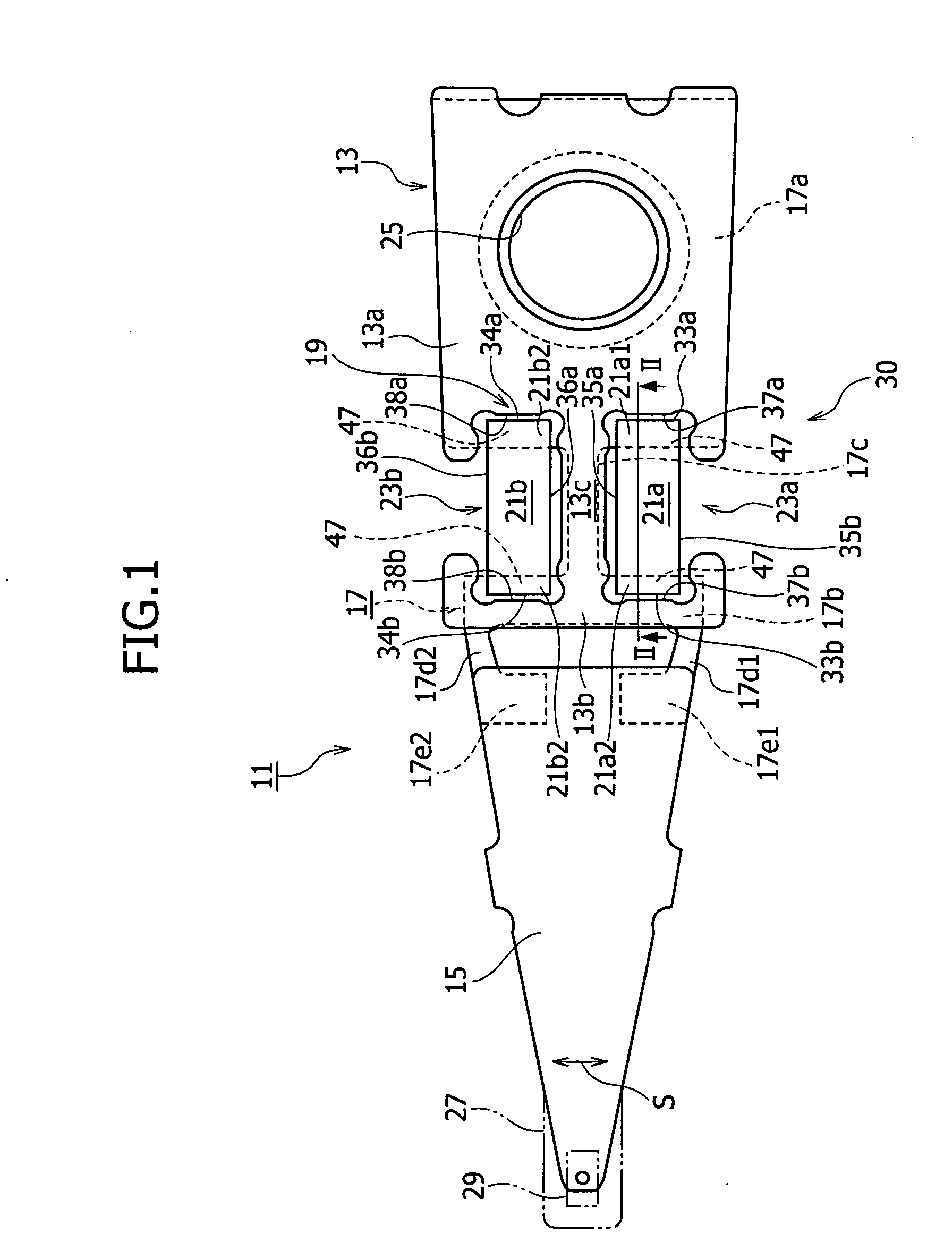
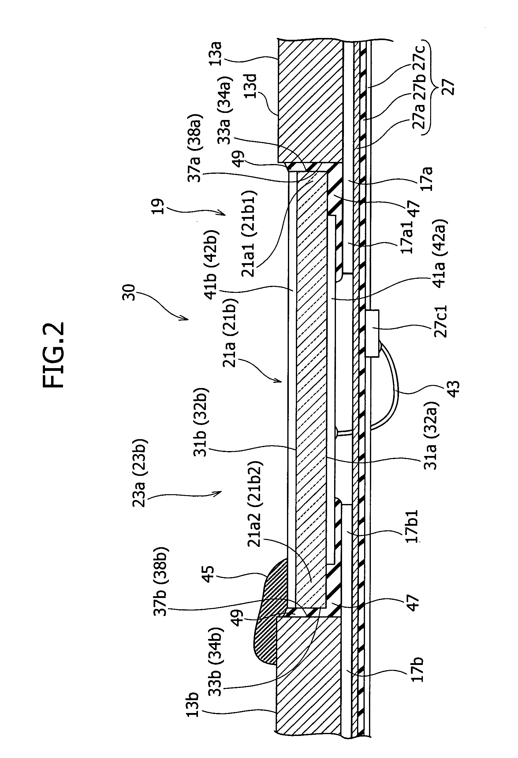
[0030]FIG. 1 is a plan view illustrating the head suspension 11 and FIG. 2 is a sectional view taken along a line II-II of FIG. 1.

[0031]The head suspension 11 of FIG. 1 employs the dual actuator system using a voice coil motor (not illustrated) and a piezoelectric actuator. The head suspension 11 has a base plate 13, a load beam 15, a hinge member 17, and the piezoelectric actuator 19.

[0032]The piezoelectric actuator 19 consists of a piezoelectric element 21 (first piezoelectric element 21a and second piezoelectric element 21b) that deforms in response to electricity applied thereto, to sl...


PUM

PropertyMeasurementUnit
Thicknessaaaaaaaaaa
Deformation enthalpyaaaaaaaaaa

Abstract

An electrode structure of a piezoelectric element is provided. The piezoelectric element 23a (23b) constitutes a piezoelectric actuator 19 attached to an attaching part 30 of an object, to minutely move a movable part 15 of the object relative to a base part 13 of the object according to deformation occurring on the piezoelectric element in response to a power applied state of the piezoelectric element. The electrode structure includes an electrode 41a formed on one of a pair of electrode forming faces 31a and 31b of the piezoelectric element on an inner side of a peripheral zone 31a1, the peripheral zone being defined along the periphery of the electrode forming face 31a on which the electrode is formed. The electrode structure also includes a non-electrode part 51 formed in the peripheral zone. Even if the peripheral zone 31a1 of the electrode forming face 31a having a short-circuit causing possibility touches the attaching part 30, no short circuit occurs.

Description

BACKGROUND OF THE INVENTION[0001]1. Field of the Invention[0002]The present invention relates generally to a head suspension of a disk drive incorporated in an information processing apparatus such as a personal computer, and particularly, to an electrode structure of a piezoelectric element used for the head suspension and a method of forming an electrode of the piezoelectric element.[0003]2. Description of Related Art[0004]Small-sized, precision information devices are rapidly advancing, and for use with such devices, needs for micro-actuators capable of conducting positioning control for very small distances are increasing. Such micro-actuators are highly needed by, for example, optical systems for correcting focuses and inclination angles, ink jet printers for controlling ink heads, and magnetic disk drives for controlling magnetic heads.[0005]To meet the needs, the applicant of the present invention has proposed in Japanese Unexamined Patent Application Publication No. 2002-501...

Claims


Application Information

Patent Timeline
IPC IPC(8): H01L41/22H01L41/047G11B5/56G11B21/10G11B21/21
CPCG11B5/4873H01L41/047Y10T29/42G11B5/4833H01L41/29G11B5/483H10N30/87H10N30/06
Inventor KASHIMA, HIDEKI
Owner NHK SPRING CO LTD
Why Eureka
Try Eureka