Method of manufacturing impeller, impeller, and compressor having impeller

a manufacturing method and technology of impellers, applied in the direction of liquid fuel engines, vessel construction, marine propulsion, etc., can solve the problem of insufficient bonding material in the bonding portion, and achieve the effect of reducing stress concentration, reducing stress concentration, and reducing stress concentration

Inactive Publication Date: 2010-08-05
TAYLOR MADE GOLF +1
View PDF3 Cites 11 Cited by
  • Summary
  • Abstract
  • Description
  • Claims
  • Application Information

AI Technical Summary

Benefits of technology

[0020]In this case, it is possible to alleviate the stress concentration generated in the bonding portion between the blade and either the cover or the disk during the rotation of the impeller. Particularly, since the edge tip of the groove is close to the side surface of the blade so as to be smoothly continuous thereto, it is possible to increase the advantage of reducing the stress concentration.
[0021]In the method of manufacturing the impell

Problems solved by technology

In addition, since it is possible to prevent the melted bonding agent from flowing outside during the bonding operation,

Method used


Image

  • Method of manufacturing impeller, impeller, and compressor having impeller
  • Method of manufacturing impeller, impeller, and compressor having impeller
  • Method of manufacturing impeller, impeller, and compressor having impeller

Examples


first embodiment

[0034]Hereinafter, a method of manufacturing an impeller and an impeller according to the present invention will be described with reference to FIGS. 1 to 4A and 4B.

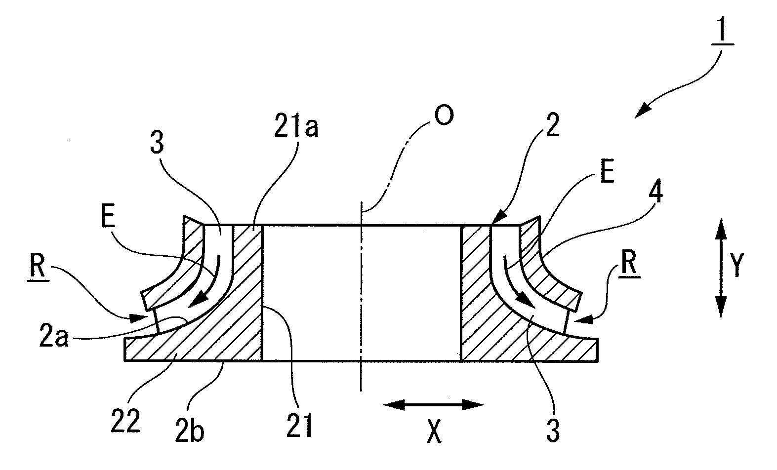
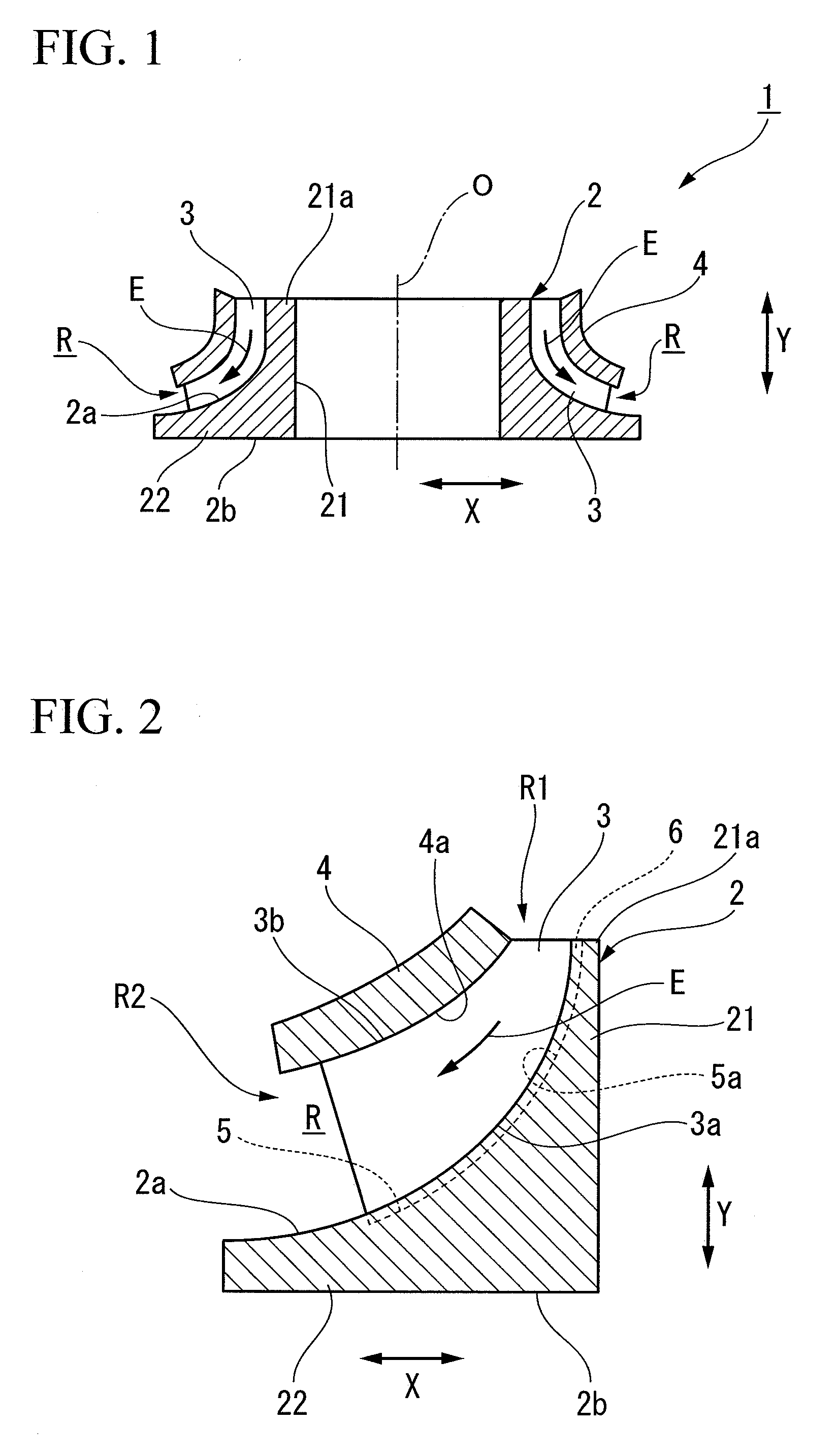
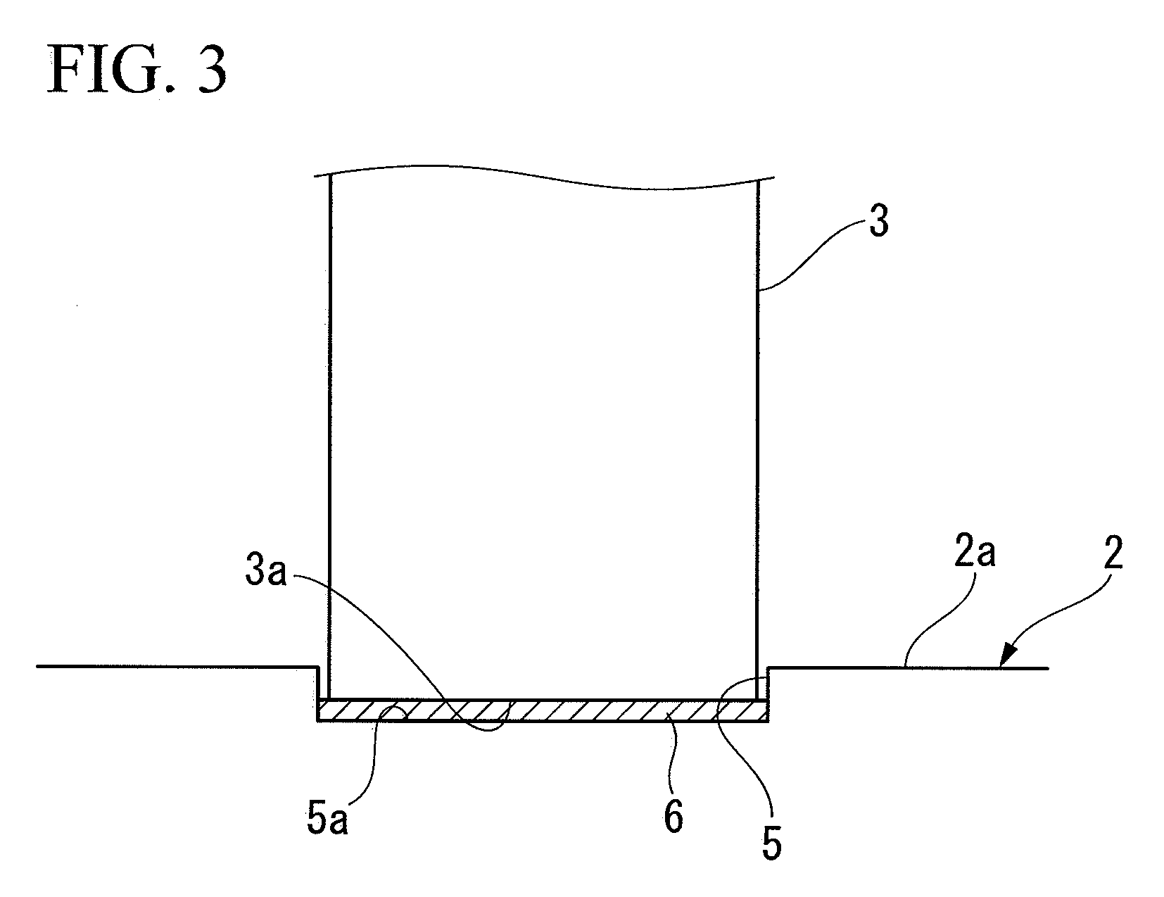
[0035]FIG. 1 is a side sectional view showing a schematic configuration of an impeller manufactured by a method of manufacturing an impeller according to a first embodiment of the present invention. FIG. 2 is a partially enlarged view showing an impeller in FIG. 1. FIG. 3 is a schematic side view showing the impeller in FIG. 2 when seen from the outer peripheral side thereof. FIG. 4A is a view showing a state before brazing in an impeller manufacturing process. FIG. 4B is a view showing a state after the brazing in the impeller manufacturing process.

[0036]The reference numeral 1 in FIG. 1 indicates an impeller manufactured by the method of manufacturing the impeller according to the first embodiment. The impeller is a rotary body which is assembled to a rotary shaft, and is mounted to a compressor such as a centrifugal c...

second embodiment

[0056]FIG. 9 is a schematic side view showing the impeller according to the present invention when seen from the outer peripheral side thereof.

[0057]In the second embodiment shown in FIG. 9, the width D1 of a groove 5A formed in the disk 2 is set to be smaller than the width D2 of the blade 3, and a protruding portion 3d is formed in the disk edge tip 3a of the blade 3 so as to be fittable to the corresponding groove 5A. In addition, filler metals indicated by the reference numeral 6A is disposed in the bottom portion 5a of the groove 5A, and filler metals indicated by the reference numeral 6B are respectively disposed in groove edges 2c of the front surface 2a of the disk 2 located on both sides of the groove 5A. That is, the groove edges 2c of the disk 2 are respectively bonded to stepped surfaces 3e formed by the protruding portions 3d of the blade 3 through the filler metals 6B.

[0058]FIG. 10 is a schematic side view showing the impeller according to a modified example of the sec...


PUM

PropertyMeasurementUnit
Shapeaaaaaaaaaa

Abstract

A method of manufacturing an impeller including a substantially disk-shaped disk, a cover facing the disk, and a blade provided between the disk and the cover, the method includes: forming a groove in a blade attachment surface of the disk or the cover so as to correspond to the shape of an edge tip of the blade; and bonding an inner surface of the groove to the edge tip of the blade through a bonding agent after inserting the edge tip of the blade into the groove.

Description

BACKGROUND OF THE INVENTION[0001]1. Field of the Invention[0002]The present invention relates to a method of manufacturing an impeller used in a centrifugal rotary machine such as a centrifugal compressor, an impeller, and a compressor having the impeller.[0003]Priority is claimed on Japanese Patent Application No. 2009-022867, filed Feb. 3, 2009, the content of which is incorporated herein by reference.[0004]2. Description of the Related Art[0005]In the past, as an impeller used in a centrifugal rotary machine such as a centrifugal compressor, there has been known a cover attachment impeller (closed impeller) including a disk attached to a rotary shaft, a cover disposed in the disk while having a gap therebetween, and plural blades connecting the disk and the cover to each other. In the impeller, a portion surrounded by a side surface of each blade and stream surfaces of the cover and the disk is formed as a passageway used to compress air. In addition, the impeller provided in the...

Claims


Application Information

Patent Timeline
IPC IPC(8): F04D29/34B23P15/04
CPCF04D29/023Y10T29/49316F04D29/624F04D29/284F05D2230/23
Inventor YAGI, NOBUYORIYANAGISAWA, EIICHIWATANABE, YUJIRO
Owner TAYLOR MADE GOLF
Why Eureka
Try Eureka