Apparatus and method for producing aligned carbon-nanotube aggregates

a technology of carbon nanotubes and aggregates, applied in the direction of aligned nanotubes, chemistry apparatus and processes, coatings, etc., can solve the problems of deterioration in the quality of aligned cnt aggregates, cnts cannot grow efficiently, and catalysts are easily deactivated, so as to prevent the adhesion of carbon contaminants to the inner wall of the formation furnace, the effect of reducing production volum

Active Publication Date: 2010-08-05
ZEON CORP +1
View PDF5 Cites 80 Cited by
  • Summary
  • Abstract
  • Description
  • Claims
  • Application Information

AI Technical Summary

Benefits of technology

[0033]Since the unit that processes the formation step and the unit that processes the growth step are provided separately, the adhesion of carbon contaminants to the inner wall of the formation furnace is prevented. Therefore, the formation step is not inhibited even in serial production, and a decrease in production volume and deterioration in quality of aligned CNT aggregates can be prevented. Further, inflow of the raw material gas into the formation furnace inhibits reduction of the catalyst in the formation step. Since the concentration of carbon atoms in the environment of the reducing gas is kept smaller than or equal to 5×10²² atoms / m3 by the means to prevent gas mixing, the reduction of the catalyst in the formation step is not inhibited, whereby the production volume and quality of aligned CNT aggregates are maintained.
[0034]Further, the fact that at least one of those components of the apparatus which are exposed to either the reducing gas or the raw material gas is composed of a heat-resistant alloy makes it easy to increase the capacity of the production apparatus, thus bringing about a profound effect in promoting realization of mass production of CNTs.
[0035]Further, the addition of a catalyst activation material to the environment surrounding the catalyst makes it possible both to maintain the activity of the catalyst and improve the growth rate of the CNTs, and to prevent a decrease in production volume and deterioration in quality of aligned CNT aggregates.
[0036]Further, the addition of a cooling unit that processes a cooling step of cooling the base material as a step following the growth step makes it possible to prevent the CNTs, the catalysts, and the base material from being oxidized, and to prevent a decrease in production volume and deterioration in quality of aligned CNT aggregates.

Problems solved by technology

In the case of a normal CVD method, fine catalyst particles are covered with carbonaceous impurities generated in the process of synthesis of CNTs; therefore, the catalyst is easily deactivated, and the CNTs cannot grow efficiently.
Because it is extremely difficult to restructure the orientation of an aggregate that is once random and non-aligned, it has been difficult to produce a CNT aggregate that is large in specific surface area with moldability and processability.
However, it was found that in the case of serial production of aligned CNT aggregates with use of the super-growth technique, there are technical problems specific to high-carbon environment and / or a catalyst activation material, although there were no such problems with the conventional synthetic method.

Method used


Image

  • Apparatus and method for producing aligned carbon-nanotube aggregates
  • Apparatus and method for producing aligned carbon-nanotube aggregates
  • Apparatus and method for producing aligned carbon-nanotube aggregates

Examples


example 1

[0161]A specific example is given below to describe in detail an apparatus according to the present invention for producing an aligned CNT aggregate.

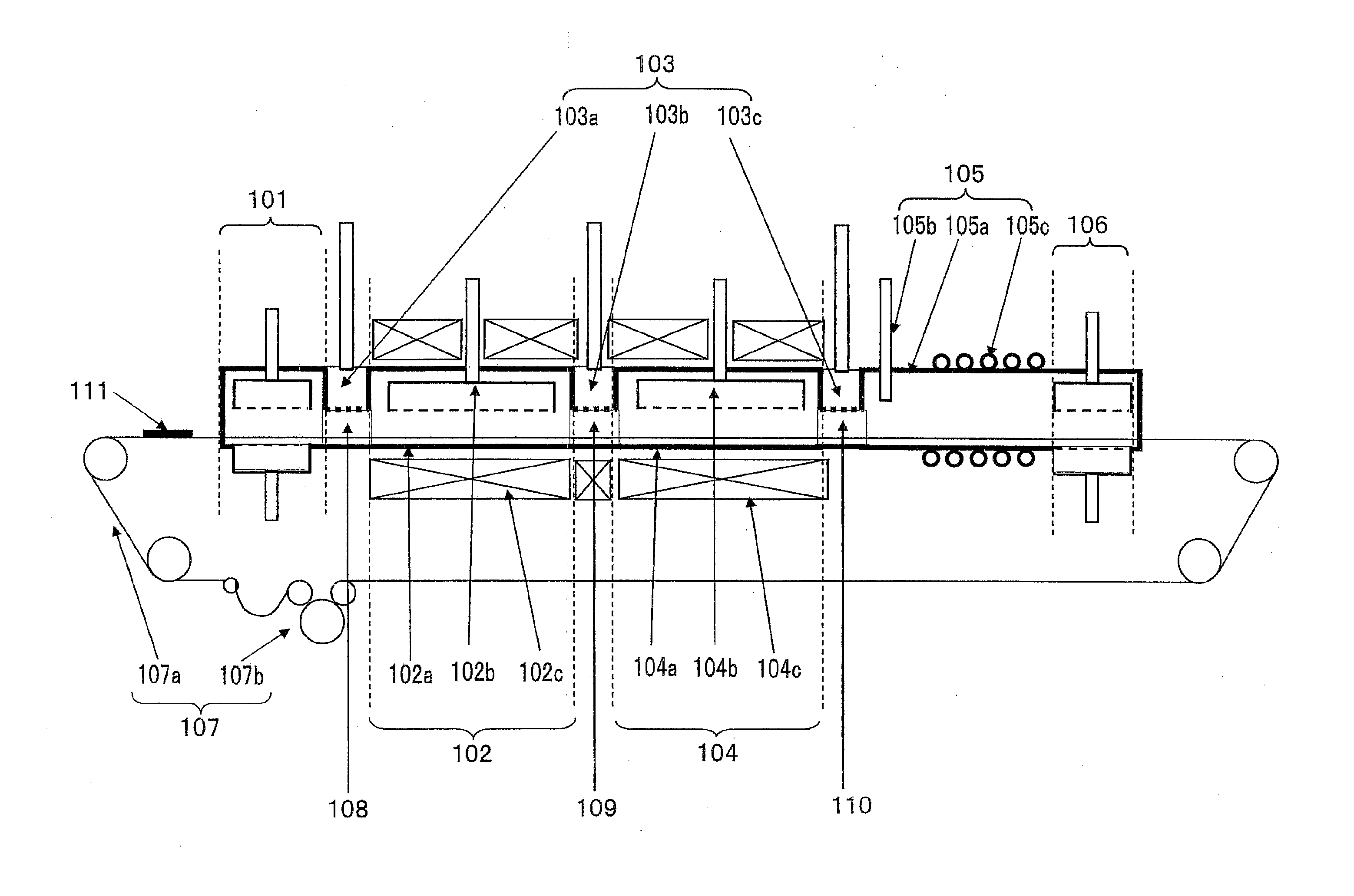
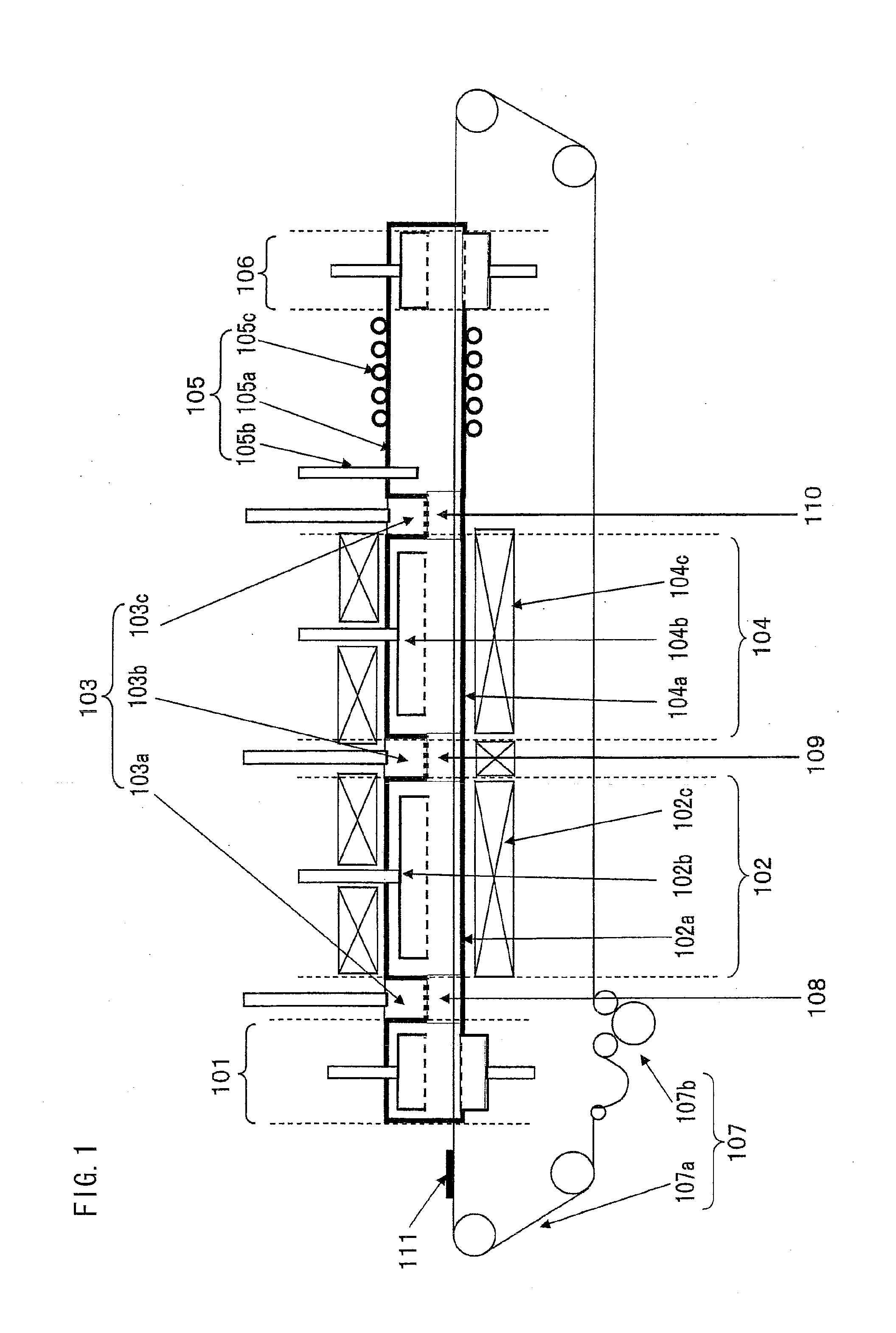
[0162]FIG. 1 shows a production apparatus of the present example. The production apparatus was constituted by an inlet purge section 101, a formation unit 102, means 103 to prevent gas mixing, a growth unit 104, a cooling unit 105, an outlet purge section 106, a transfer unit 107, and connecting sections 108 to 110. The respective furnaces and injections sections of the formation / growth units, the exhaust sections of the means to prevent gas mixing, the mesh belt, and the connecting sections were made of SUS 310 plated with aluminum.

[0163]The conditions for production of a catalyst substrate are described below. The substrate used was a 90 mm×90 mm Fe—NI—Cr alloy YEF 426 (Ni 42%, Cr 6%; manufactured by Hitachi Metals, Ltd.) with a thickness of 0.3 mm. The surface roughness was measured using a laser microscope, and it was found that the...

example 2

[0191]A specific example is given below to describe in detail an apparatus according to the present invention for producing an aligned CNT aggregate.

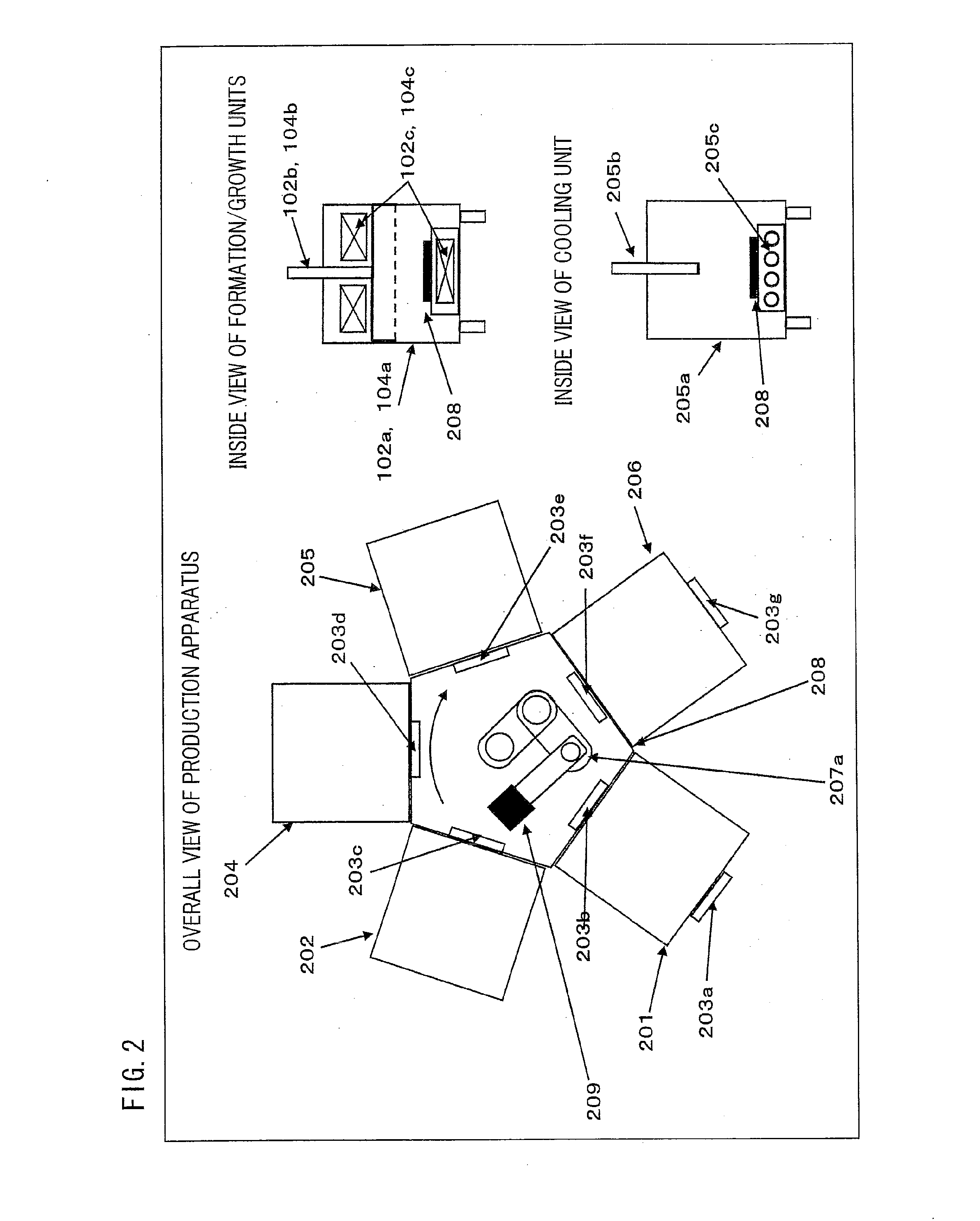
[0192]FIG. 2 shows a production apparatus of the present example. The production apparatus was constituted by an inlet purge section 201, a formation unit 202, gate valves 203a to 203g, a growth unit 204, a cooling unit 205, an outlet purge section 206, a transfer unit 207, and a connecting section 208. The respective furnaces and injections sections of the formation / growth units, the robot arm, and the connecting section were made of SUS 310 plated with aluminum.

[0193]The conditions for production of a catalyst substrate are described below. The substrate used was a 90 mm×90 mm Fe—NI—Cr alloy YEF 426 (Ni 42%, Cr 6%; manufactured by Hitachi Metals, Ltd.) with a thickness of 0.3 mm. The surface roughness was measured using a laser microscope, and it was found that the arithmetic average roughness was Ra≈ 2.1 μm. Alumina films with a thic...


PUM

PropertyMeasurementUnit
temperatureaaaaaaaaaa
specific surface areaaaaaaaaaaa
weight densityaaaaaaaaaa

Abstract

An apparatus of the present invention for producing an aligned carbon-nanotube aggregate is an apparatus for producing an aligned carbon-nanotube aggregate by synthesizing the aligned carbon-nanotube aggregate on a base material having a catalyst on a surface thereof, the apparatus including: a formation unit that processes a formation step of causing an environment surrounding the catalyst to be an environment of a reducing gas and heating at least either the catalyst or the reducing gas; a growth unit that processes a growth step of synthesizing the aligned carbon-nanotube aggregate by causing the environment surrounding the catalyst to be an environment of a raw material gas and by heating at least either the catalyst or the raw material gas; and a transfer unit that transfers the base material at least from the formation unit to the growth unit. Thus provided is a production apparatus and a production method that are capable of improving efficiency in the production of aligned CNT aggregates by preventing a decrease in production volume and deterioration in quality of aligned CNT aggregates in serial production and by making it easy to increase the size of the apparatus.

Description

TECHNICAL FIELD[0001]The present invention relates to apparatuses for producing aligned carbon-nanotube aggregates and, in particular, to an apparatus and method for producing an aligned carbon-nanotube aggregate, the apparatus and method being capable of remarkably improving production efficiency without entailing deterioration in quality during serial production.BACKGROUND ART[0002]Carbon nanotubes (hereinafter referred to also as “CNTs”) are carbon structures each structured such that a carbon sheet composed of a planar hexagonal arrangement of carbon atoms is sealed in a cylindrical shape. The CNTs are classified into single-walled CNTs and multiwall CNTs, both of which are expected to develop into functional materials such as electronic device materials, optical element materials, and conducting materials because of their mechanical strength, optical properties, electrical properties, thermal properties, and molecular-adsorbing functions, etc.[0003]Among the CNTs, the single-wa...

Claims


Application Information

Patent Timeline
Patent Type & Authority Applications(United States)
IPC IPC(8): C23C16/44C23C16/00
CPCB82Y30/00B82Y40/00C01B31/0233C23C16/26C01B2202/08C01P2004/13C23C16/0281C01B31/024C01B32/162C01B32/164B82B3/0004B82B3/0009B82B3/0066
Inventor SHIBUYA, AKIYOSHIKAWATA, KEIICHIARAKAWA, KOHEIHATA, KENJIYUMURA, MOTOO
Owner ZEON CORP
Why Eureka
Try Eureka