Mold manufacturing of an object comprising a functional element, transfering process and object

a technology of functional elements and molds, applied in the direction of metal layered products, synthetic resin layered products, packaging, etc., can solve the problems of large gap between objects and functional elements, increase in the total thickness or volume of objects, and the inability to manufacture objects through a continuous process

Inactive Publication Date: 2010-08-05
SIPIX CHEM
View PDF15 Cites 34 Cited by
  • Summary
  • Abstract
  • Description
  • Claims
  • Application Information

AI Technical Summary

Benefits of technology

[0011]When a functional element is embedded in the surface of an object, the seamless integration produces a very appealing look. The functional element may conform to the shape of the object, even if the surface is curved. As a result, the functional element may appear as an integral part of the object.

Problems solved by technology

In other words, the object cannot be manufactured by a continuous process.
In addition, the mechanical integration or lamination process typically results in a large gap between the object and the functional element and also an increase in the total thickness or volume of the object.
As a result, the current methods are not only time-consuming but also labor intensive.
In addition, in order to meet desired specifications, such as style, compactness, durability, and other features that are important for handheld devices, the current methods could be prohibitively costly.
However, the spraying not only brings environment contamination but also wastes a lot of spraying material and increases, cost.
While the conventional IMD is applied on the object having non-planar surface, the transferred pattern at a curved surface of the object may crack easily, the transfer film may be wrinkled up, and bubbles may exist between the transfer film and the object.
However, the functional element disposed in the transfer film may be damaged by the high temperature and high pressure during the IMD.

Method used


Image

  • Mold manufacturing of an object comprising a functional element, transfering process and object
  • Mold manufacturing of an object comprising a functional element, transfering process and object
  • Mold manufacturing of an object comprising a functional element, transfering process and object

Examples


Embodiment Construction

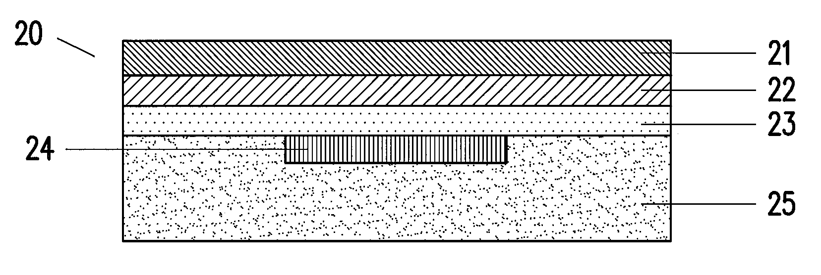
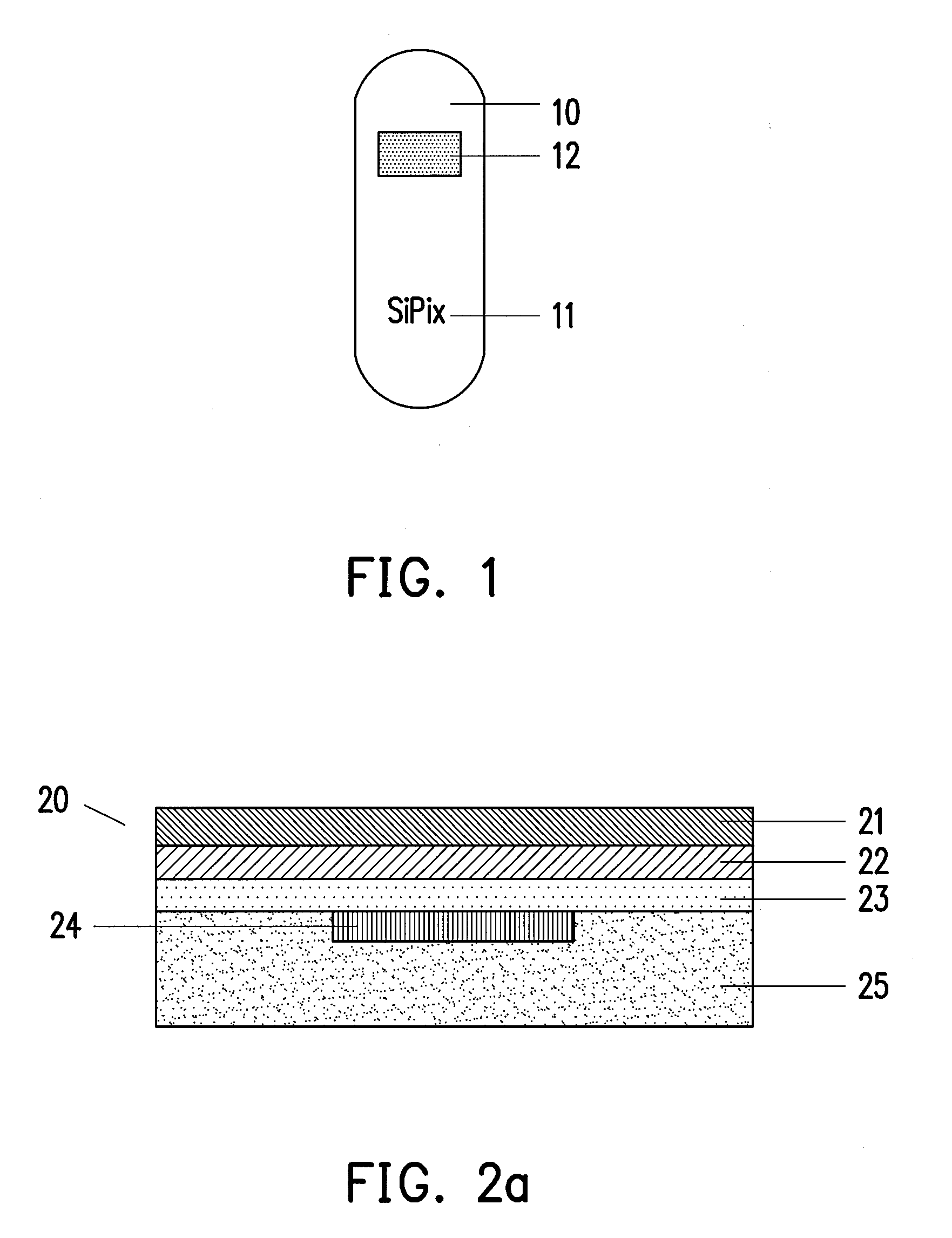
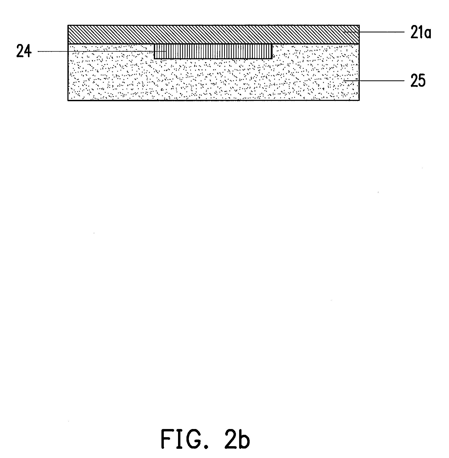
[0035]The term “functional element” referred to throughout this application broadly includes any electrical or mechanical elements which are capable of performing a function. Examples of such functional elements may include, but are not limited to, optical components, optical devices, waveguides, electronic designs such as conductive or semi-conductive electrical traces, and electronic components such as integrated circuits, printed electrical circuits, transistors, diodes, resistors, inductors, capacitors, antennas, RFID transponders, batteries, solar cells, light-emitting diodes (LEDs), and other diodes not limited to LED, organic light-emitting diodes (OLEDs), display components, backlight components, speakers, microphones, push buttons, touch panels, touch pads, connectors and the like.

[0036]The term “embedded in the top surface”, in the context of the present invention, is intended to indicate that the functional element is integrated into the top surface of an object when the ...


PUM

PropertyMeasurementUnit
Temperatureaaaaaaaaaa

Abstract

This invention relates to an object having a functional element embedded in its top surface and processes for its manufacturing. The object is in general formed by molding, stamping, lamination or a combination thereof. The functional element is includes any electrical or mechanical elements that are capable of performing a function.

Description

CROSS-REFERENCE TO RELATED APPLICATION[0001]This is a continuation-in-part application of and claims priority benefit of patent application Ser. No. 11 / 513,333, filed on Aug. 29, 2006, which claims the priority benefit of U.S. provisional application No. 60 / 721,861 filed on Sep. 28, 2005. The entirety of each of the above-mentioned patent applications is hereby incorporated by reference herein and made a part of this specification.BACKGROUND OF THE INVENTION[0002]1. Field of the Invention[0003]This invention relates to an object comprising a functional element embedded in its surface, processes for its manufacture, a transferring process and an object processed with the transferring process.[0004]2. Description of Related Art[0005]Currently, for an object having a functional element, the object and the functional element are manufactured separately and the two components are then assembled together. The assembly of such an object usually requires mechanical integration or lamination...

Claims


Application Information

Patent Timeline
IPC IPC(8): B32B27/36B32B37/12B29C45/14B32B7/12B32B3/02B32B27/42B32B27/40B32B27/32B32B27/38B32B27/30B32B27/28B29C45/02
CPCB29C43/06Y10T428/2839B29C43/20B29C43/56B29C45/14778B29C45/14811B29C45/14827B29C49/20B29C51/12B29C63/0047B29C63/04B29C2043/561B29C2791/006B29K2033/20B29K2077/10B29K2715/006B29L2031/3061H05K3/0058H05K3/20Y10T156/10Y10T428/239B29C43/18Y10T428/31515Y10T428/31721Y10T428/31855Y10T428/31725Y10T428/31507Y10T428/31942Y10T428/31938Y10T428/31786Y10T428/31551
Inventor LIAO, CHIH-YUANHO, ANDREWWANG, SHUN-CHENGHUANG, SHIH-MIN
Owner SIPIX CHEM
Why Eureka
Try Eureka