Cell analysis apparatus and cell analysis method

a cell analysis and cell technology, applied in the field of cell analysis apparatus and cell analysis method, can solve the problems of analysis apparatus disclosed, signal waveform of forward-scattered light, and limited improvement of the accuracy of distinguishing between aggregating cells

Active Publication Date: 2010-08-05
SYSMEX CORP
View PDF10 Cites 12 Cited by
  • Summary
  • Abstract
  • Description
  • Claims
  • Application Information

AI Technical Summary

Benefits of technology

[0007]The present invention has been made in view of the situation as described above. It is an objective of the present invention to provide a cell analysis apparatus and a cell analysis method which is capable of distinguishing between aggregating cells and non-aggregating cells accurately.

Problems solved by technology

This consequently may cause a signal waveform of forward-scattered light that has unclear peak and trough.
Thus, the analysis apparatus disclosed in WO publication No. 2006 / 103920 is limited in the improvement of the accuracy of distinguishing between aggregating cells and non-aggregating cells.

Method used


Image

  • Cell analysis apparatus and cell analysis method
  • Cell analysis apparatus and cell analysis method
  • Cell analysis apparatus and cell analysis method

Examples


Embodiment Construction

[0033]The following section will describe in detail an embodiment of a cell analysis apparatus and a cell analysis method of the present invention with reference to the attached drawings.

Entire Configuration of Cell Analysis Apparatus

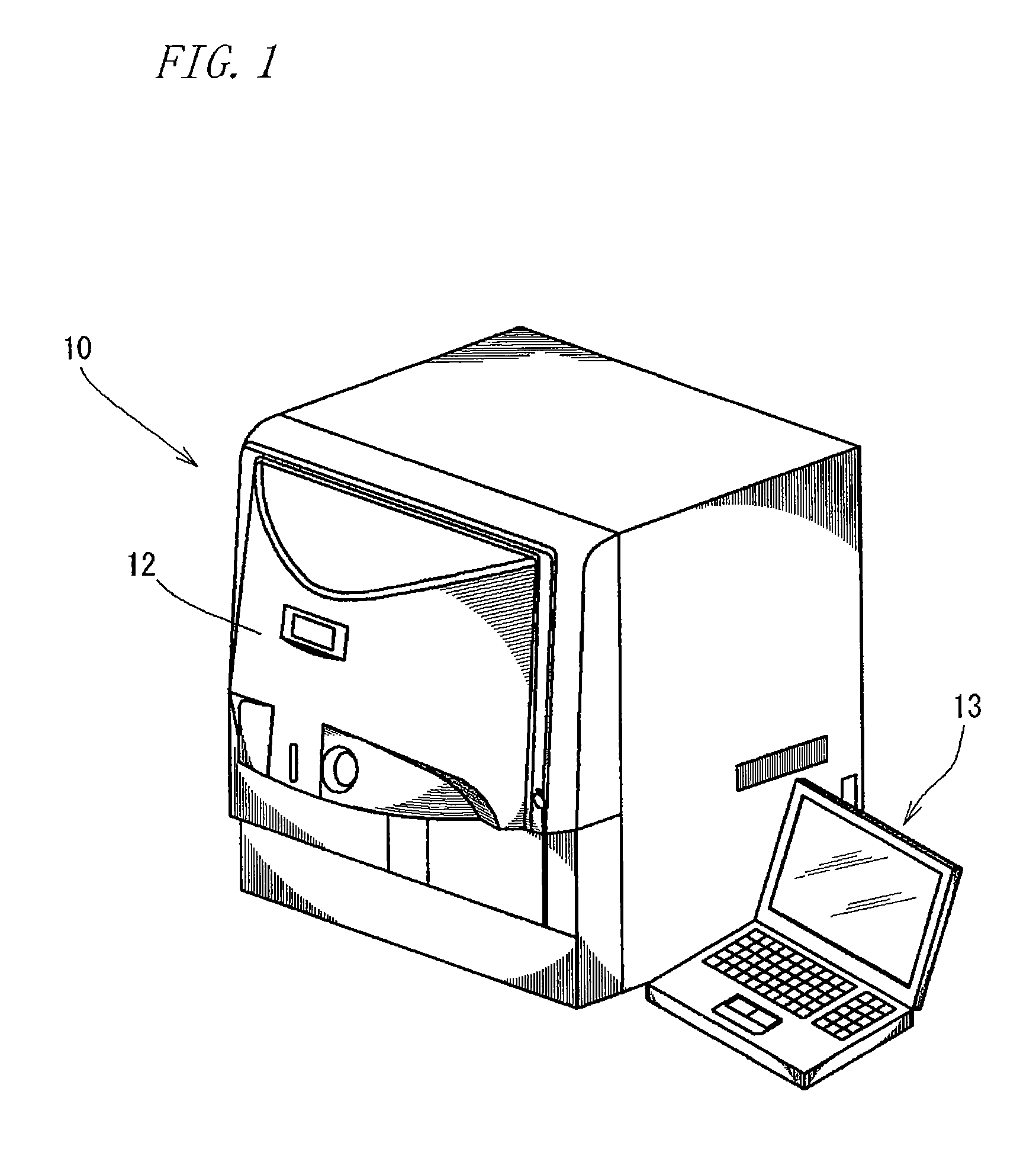
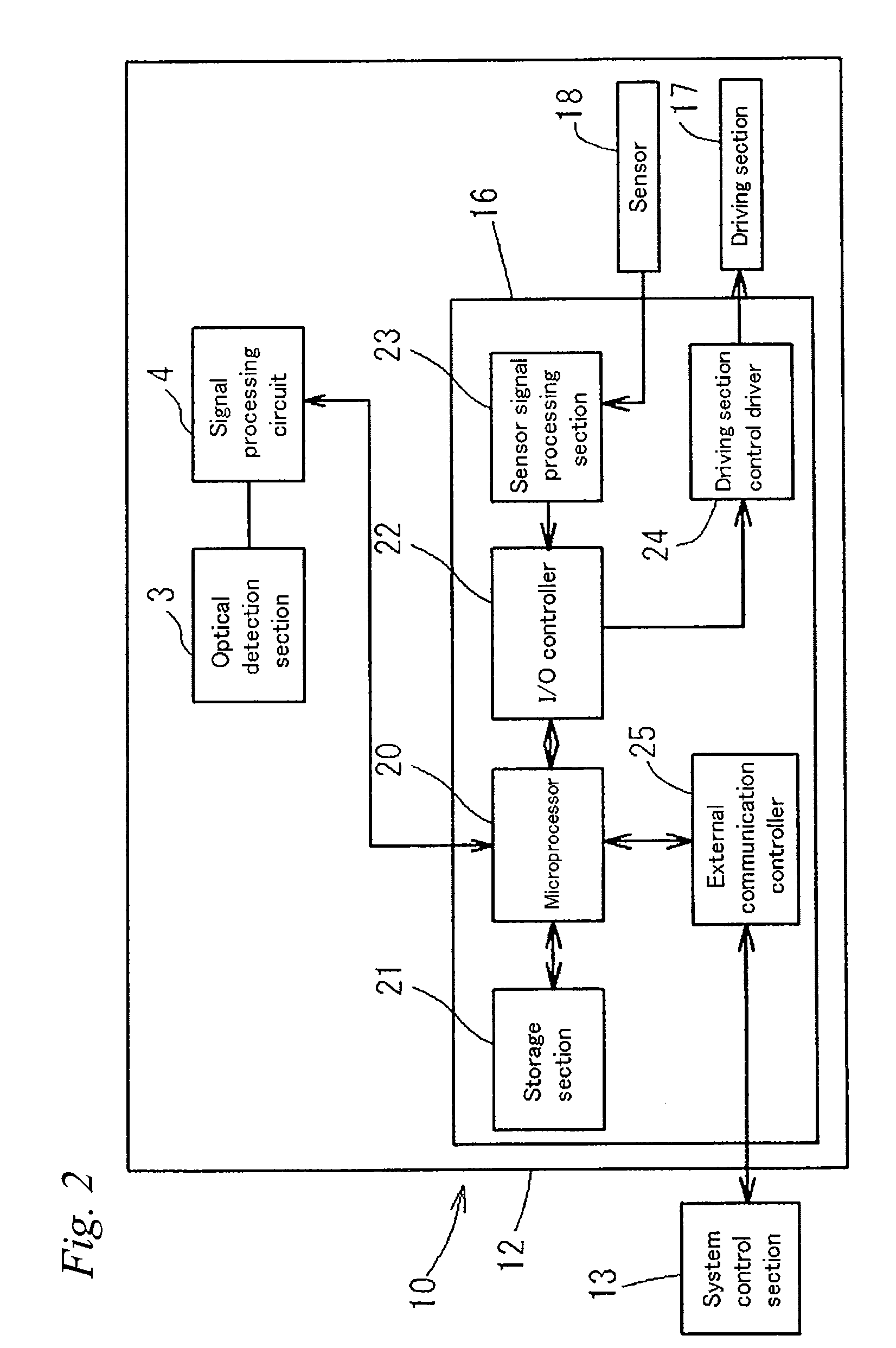
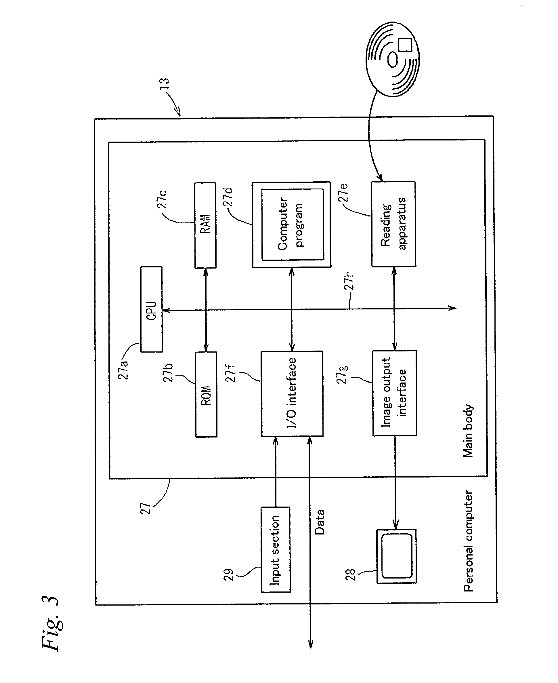
[0034]FIG. 1 is a perspective view illustrating a cell analysis apparatus 10 according to one embodiment of the present invention. The cell analysis apparatus 10 is used for the following process. Specifically, a measurement sample including cells collected from a patient is caused to flow into a flow cell. Then, the measurement sample flowing in the flow cell is irradiated with laser beam. Then, the light from the measurement sample (e.g., forward-scattered light or lateral fluorescence) is detected and analyzed to thereby determine whether the cells include cancer and atypical cells or not. Specifically, the cell analysis apparatus 10 is used for screening a cervical cancer by using epithelial cells of the endocervix. The cell analysis apparatus 10 in...


PUM

PropertyMeasurementUnit
diameteraaaaaaaaaa
diameteraaaaaaaaaa
sizeaaaaaaaaaa

Abstract

A cell analysis apparatus that can accurately distinguish between an aggregating cell and a non-aggregating cell is provided. The cell analysis apparatus (10) includes: an optical detection section (3) for flowing a measurement sample obtained from a biological sample and a pigment into a flow cell (51), irradiating the measurement sample flowing in the flow cell (51) with laser beam and detecting fluorescence from the measurement sample; a signal processing circuit (4) for acquiring, based on a fluorescence signal outputted from the detection section (3), a value reflecting the height of a waveform of the signal and a value reflecting the length of a ridge line of the waveform of the signal; and a system control section (13) for distinguishing between an aggregating cell formed by aggregation of a plurality of cells and a non-aggregating cell, based on the value reflecting the height of the waveform of the fluorescence signal and the value reflecting the length of the ridge line of the waveform of the fluorescence signal obtained by the signal processing circuit (4).

Description

RELATED APPLICATIONS[0001]This application is a continuation of PCT / JP2008 / 069338 filed on Oct. 24, 2008, which claims priority to Japanese Application No. JP2007-280738 filed on Oct. 29, 2007. The entire contents of these applications are incorporated herein by reference.TECHNICAL FIELD[0002]The present invention relates to a cell analysis apparatus and a cell analysis method. More particularly, the present invention relates to a cell analysis apparatus and a cell analysis method by which a measurement sample flowing in a flow cell is illuminated with laser beam and the light from the measurement sample is used to analyze cells in the measurement sample.BACKGROUND ART[0003]Flow cytometry method for illuminating a measurement sample including cells as a measuring object with laser beam and measuring the size and shape of each cell by using scattered light and fluorescence from the measurement sample, is disclosed in WO publication No. 2006 / 103920 for example. According to this flow ...

Claims


Application Information

Patent Timeline
Patent Type & Authority Applications(United States)
IPC IPC(8): C12Q1/68C12M1/34C12Q1/02
CPCG01N15/147G01N21/6486G01N2015/1497G01N2015/0092
Inventor ISHISAKA, MASAKIKISHI, KAZUKIFUKUDA, MASAKAZU
Owner SYSMEX CORP
Why Eureka
Try Eureka