
Method for operating a vehicle brake system and vehicle brake system

a technology for brake systems and vehicles, applied in brake systems, vehicle positioning/course/altitude control, instruments, etc., can solve problems such as loss of driving stability, vehicle veering or skidding, etc., to prevent rear axle overbraking and loss of vehicle driving stability

Active Publication Date: 2010-08-05
CONTINENTAL TEVES AG & CO OHG
View PDF2 Cites 44 Cited by
  • Summary
  • Abstract
  • Description
  • Claims
  • Application Information

AI Technical Summary

Benefits of technology

[0009]An object of the invention is therefore to provide a method for operating a vehicle brake system which prevents overbraking of the rear axle and therefore loss of vehicle driving stability, and also a corresponding vehicle brake system.
[0012]In one preferred exemplary embodiment, the maximum drag torque value of each rear axle is lower than the minimum of the drag torques which are present at the front axles. Overbraking of the rear axles is therefore effectively prevented because it is ensured, even when there are a plurality of rear axles, that the rear axles are not subjected to overbraking and can therefore supply the necessary lateral forces for ensuring stability of the motor vehicle.
[0018]In a further exemplary embodiment, the open-loop and / or closed-loop control of the drag torque which is present at the respective axle is carried out as a result of at least one wheel dynamics characteristic variable being monitored with respect to a sudden reduction in adhesion between a tire or tires and the underlying surface, for example the wheel rotational speed, the wheel rotational acceleration, the vehicle longitudinal acceleration, the vehicle speed and / or the wheel load. The occurrence of a sudden reduction in adhesion can be detected, for example, by a sudden increase in the rotational speed of the respective vehicle wheel. A sudden reduction in adhesion has the result that the maximum drag torque value which is to be assigned to the corresponding axle is also exceeded. In such a case, the drag torque which is present at this axle is firstly reduced by reducing the regeneration portion of the braking force for this axle. If no regeneration torque is present at the axle or the regeneration torque is already reduced to a maximum degree, the conventional braking force which is present at the axle is then reduced. In particular it is advantageous if the system (regeneration portion or portion of the conventional braking force) with the relatively high dynamics is reduced so that the vehicle wheel is quickly adjusted out of the range in which there is a risk of a sudden reduction in adhesion, and a stable state is achieved. With respect to the wheel load it is to be noted that the maximum drag torque value also depends on the wheel load since the wheel load determines the force acting vertically on the contact region between the underlying surface and the vehicle wheel.

Problems solved by technology

Since no lateral guidance forces can be transmitted any longer at an overbraked rear axle, this leads to a loss of driving stability, which can result in the vehicle veering or skidding.

Method used


Image

  • Method for operating a vehicle brake system and vehicle brake system
  • Method for operating a vehicle brake system and vehicle brake system

Examples


Embodiment Construction

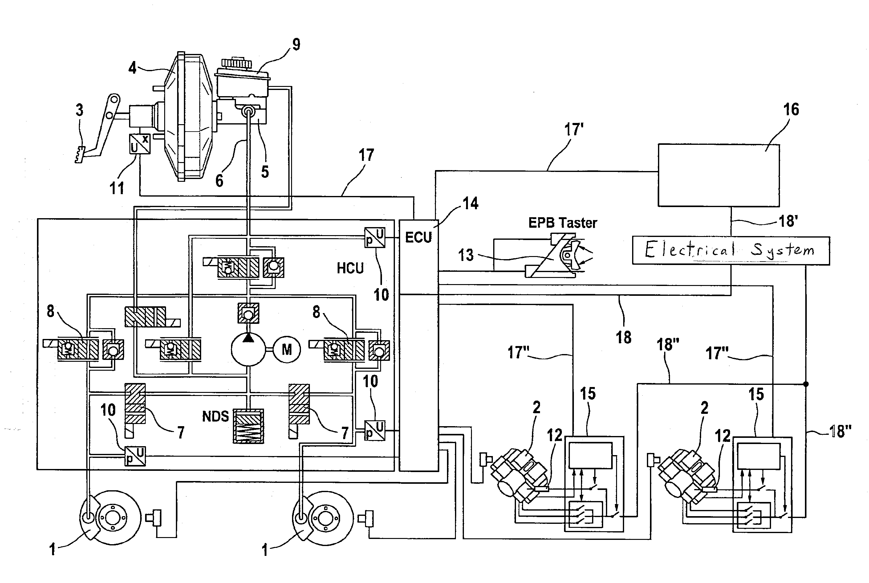
[0027]The vehicle brake system which is illustrated schematically in the circuit diagram and with which the present method can be carried out has hydraulically actuable wheel brakes 1 and electromechanically actuable wheel brakes 2. The hydraulically actuable wheel brakes 1 are arranged on a first axle, the front axle of the motor vehicle, and hydraulic pressure medium is applied to them by means of a pedal-actuated vacuum brake booster 4 with master cylinder 5 connected downstream. For this purpose, the hydraulically actuable wheel brakes 1 are connected to the master cylinder 5 via a hydraulic line 6 with intermediate connection of inlet valves 8. When there is a reduction in pressure, the applied pressure medium is discharged via outlet valves 7 into a pressureless pressure medium reservoir vessel 9. In order to measure the applied hydraulic pressure and to carry out control processes, such as anti-lock brake control processes, a plurality of pressure sensors 10 are provided, the...


PUM


Abstract

A method for operating a vehicle braking system for motor vehicles including a hybrid or electric drive and hydraulically actutable wheel brakes on the front axle, wherein the wheels associated with the rear axle are driven at least partially by an electric motor that can be operated as a generator to recover braking energy and, in generator mode, exerts a braking force on the vehicle wheel associated with the respective axle, thereby generating a drag torque including the braking torque and the regeneration torque of the electric drive, the drag torque being separately regulatable on the front and rear axles. To prevent overbraking of the rear axle and a loss of driving stability of the vehicle, a regeneration torque acting on the rear axle is controlled or regulated such that the drag torque acting on the rear axle does not exceed a maximum drag torque value associated with that axle.

Description

CROSS REFERENCE TO RELATED APPLICATIONS[0001]This application is the U.S. national phase application of PCT International Application No. PCT / EP2008 / 054014, filed Apr. 3, 2008, which claims priority to German Patent Application No. DE 10 2007 016 422.1, filed Apr. 5, 2007 and German Patent Application No. DE 10 2008 017 478.5, filed Apr. 3, 2008, the contents of such applications being incorporated herein by reference.1. FIELD OF THE INVENTION[0002]The invention relates to a method for operating a vehicle brake system, in particular for motor vehicles having a hybrid drive or electric drive, having preferably hydraulically actuable wheel brakes, which apply a braking torque, at one or more of the vehicle axles, in particular a front axle, wherein in particular the vehicle wheels which are assigned to a rear axle are driven at least partially by an electric motor which can be operated as a generator in order to recover (regenerate) braking energy, and in the generator mode said elect...

Claims


Application Information

Patent Timeline
IPC IPC(8): B60L7/18G06F19/00B60W10/18B60W30/18
CPCB60L7/18B60T1/10B60T8/1766B60T8/267B60T8/4872B60T13/686Y02T10/56B60T2270/608B60W10/08B60W10/184B60W20/00B60W30/18127B60W30/18172B60T2201/09B60W2050/0031B60W2520/30B60W2540/12Y02T10/40
Inventor STOLZL, STEPHANFISCHER, DANIELSEURER, FRANK
Owner CONTINENTAL TEVES AG & CO OHG
Learn More