
Control device of hybrid vehicle

a control device and hybrid technology, applied in mechanical equipment, propulsion parts, transportation and packaging, etc., can solve the problems of uncontrollable hydraulic pressure to the clutch, disadvantageous complexity of the hydraulic control circuit, and negative effect, so as to reduce the slip time of the clutch, suppress the drag torque of the engine, and reduce the effect of the clutch slip tim

Inactive Publication Date: 2014-06-12
TOYOTA JIDOSHA KK
View PDF2 Cites 18 Cited by
  • Summary
  • Abstract
  • Description
  • Claims
  • Application Information

AI Technical Summary

Benefits of technology

The technology described in this patent allows for smoother operation of a hybrid vehicle by reducing uncomfortable feelings caused by incorrect engagement of the clutch between the engine and motor generator. This is achieved by changing the engine's rotation speed to match that of the motor generator, which reduces drag torque and the feeling of deceleration. Additionally, the technology allows for improved efficiency and greater use of the vehicle's power sources by optimizing power transmission through the use of a second clutch. Overall, this technology simplifies the process of engaging the clutch and reduces the driver's discomfort during the transition to hybrid operation.

Problems solved by technology

However, for example, in a configuration with the hydraulic pressure to the clutch controlled by one linear solenoid valve (single system), the conventional technique has a negative effect because if the wrong engagement of the clutch is attributable to breaking of wire etc., in the linear solenoid valve, the hydraulic pressure to the clutch becomes uncontrollable and the conventional technique cannot deal with the wrong engagement.
For example, in a configuration including a linear solenoid valve Sol.1 along with a switching solenoid valve Sol.2 and a switching valve SV as depicted in FIG. 11 to control the hydraulic pressure to the clutch with these valves (duplex system), the conventional technique can deal with the wrong engagement; however, a hydraulic control circuit disadvantageously becomes complicated in this form.
Therefore, a control device of a hybrid vehicle is not yet developed at present that reduces a driver's uncomfortable feeling in a simplified manner in a case of wrong engagement of a clutch disposed between an engine and a motor generator.

Method used


Image

  • Control device of hybrid vehicle
  • Control device of hybrid vehicle
  • Control device of hybrid vehicle

Examples


embodiment

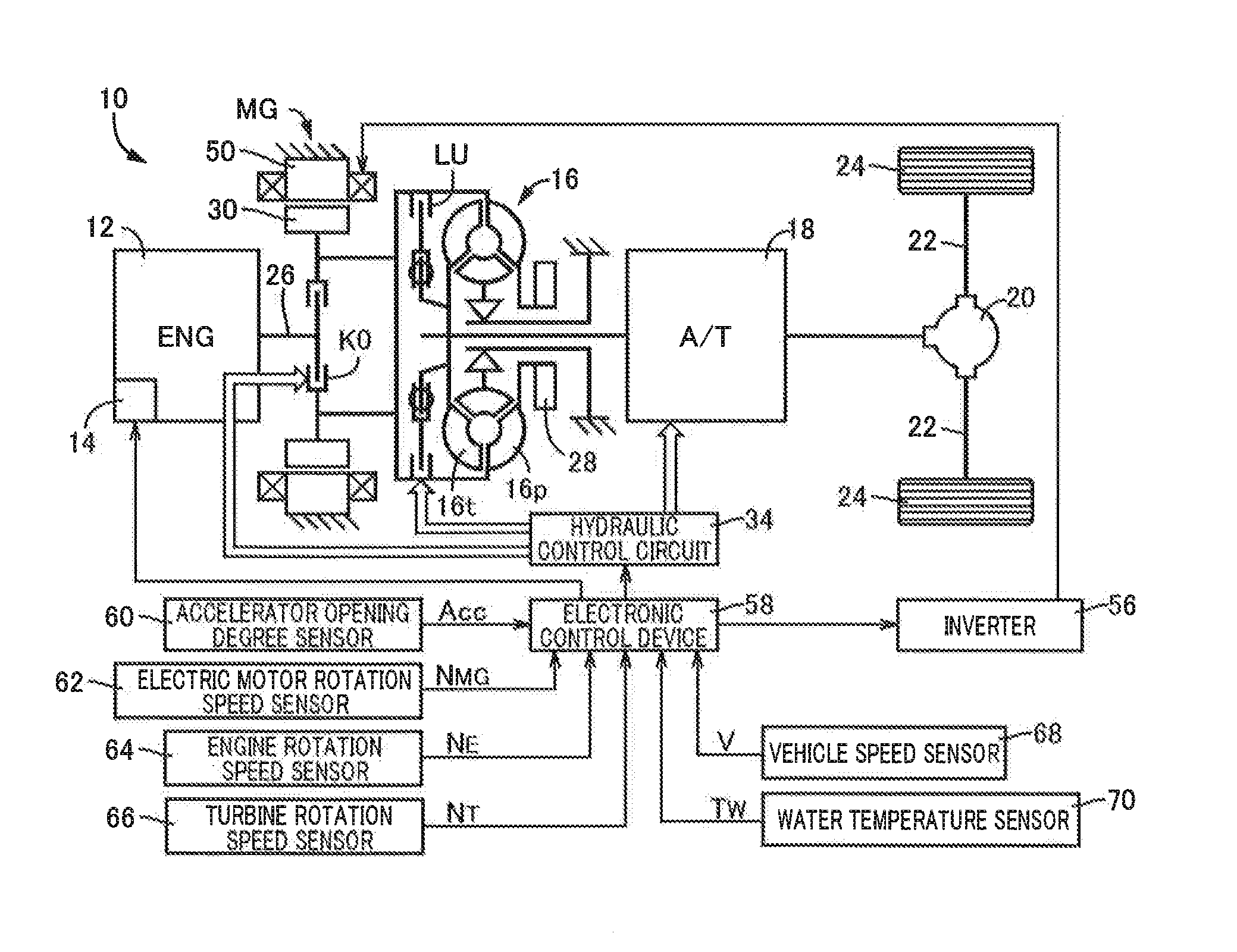
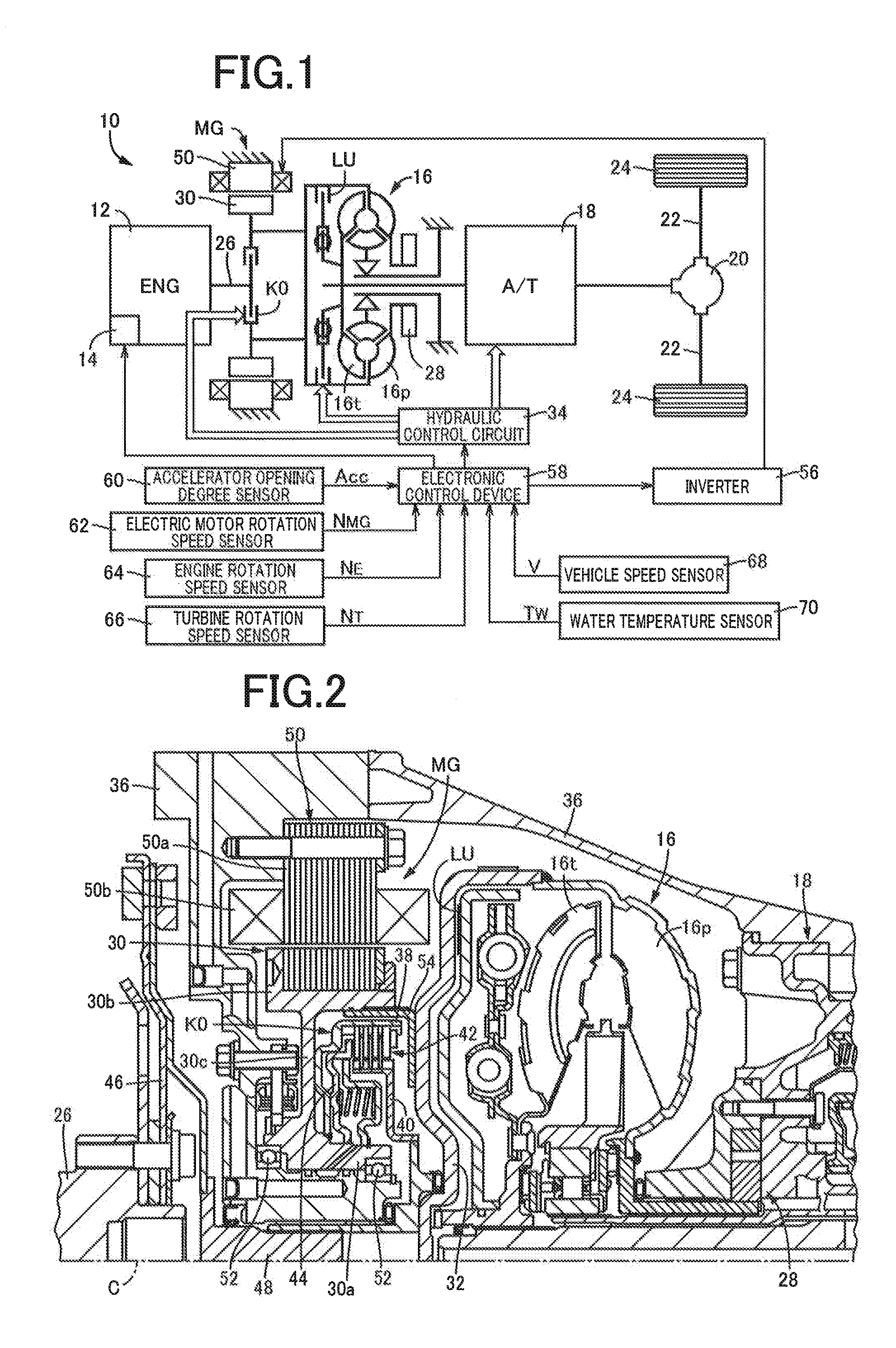
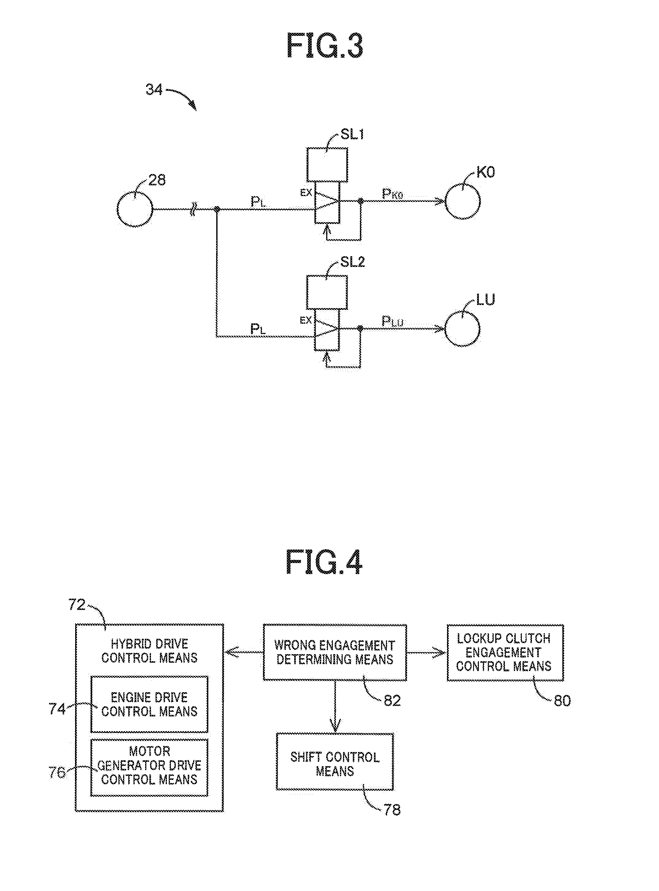
[0024]FIG. 1 is a conceptual diagram of a drive system according to a control device of a hybrid vehicle that is one embodiment of the present invention. A hybrid vehicle 10 depicted in FIG. 1 includes an engine 12 and a motor generator MG acting as drive sources and drive power generated by the engine 12 and the motor generator MG is transmitted through each of a torque converter 16, an automatic transmission 18, a differential gear device 20, and a pair of left and right axles 22 to a pair of left and right drive wheels 24. Because of this configuration, the hybrid vehicle 10 is driven by using at least one of the engine 12 and the motor generator MG as a drive source for running. Therefore, the hybrid vehicle 10 selectively establishes any one of engine running using only the engine 12 as the drive source for running, EV running (motor running) using only the motor generator MG as the drive source for running, and hybrid running using the engine 12 and the motor generator MG as t...


PUM


Abstract

In a case of engagement when a clutch K0 disposed between an engine 12 and a motor generator MG is engaged during EV running while a release instruction for the clutch K0 is output, drive of the engine 12 is changed such that a rotation speed NE of the engine 12 approaches a rotation speed NMG of the motor generator MG and, therefore, a drag torque of the engine 12 can be suppressed regardless of an engagement state of the clutch K0, and generation of longitudinal acceleration can be suppressed by reducing a slip time of the clutch K0. Therefore, a control device of a hybrid vehicle 10 can be provided that reduces a driver's uncomfortable feeling in a simplified manner in a case of wrong engagement of the clutch K0.

Description

TECHNICAL FIELD[0001]The present invention relates to a control device of a hybrid vehicle including a clutch in a power transmission path between an engine and a motor generator and particularly to an improvement for reducing a driver's uncomfortable feeling in a simplified manner in a case of wrong engagement of the clutch.BACKGROUND ART[0002]A hybrid vehicle is known that includes a clutch in a power transmission path between an engine and a motor generator for controlling a power transmission through the power transmission path depending on an engagement state and that interrupts the power transmission through the power transmission path by releasing the clutch during EV running while only the motor generator is used as a drive source for running. Although a normally close type (normally-closed) hydraulic friction engagement device is preferably used as the clutch, if the clutch is wrongly engaged due to, for example, a failure of an electromagnetic control valve, a drag torque ...

Claims


Application Information

Patent Timeline
Patent Type & Authority Applications(United States)
IPC IPC(8): B60W20/00
CPCY10S903/946B60W20/40B60K6/48B60W10/02B60W10/06B60W10/08B60W30/192B60Y2300/64B60W10/10B60W2510/0638B60W2510/081B60W2710/0644B60W2710/1005B60W20/50F16D48/06F16D2500/1066F16D2500/3067F16D2500/3108F16D2500/3144F16D2500/5122F16D2500/70454F16D2500/70468B60K2006/4825Y02T10/40Y02T10/62
Inventor MIYAZAKI, TERUFUMIIDESHIO, YUKIHIKOKAMIYA, TOSHIHIKOETO, SHINGOASAOKA, HIRONORIKATO, YASUYUKI
Owner TOYOTA JIDOSHA KK
Learn More