Gas turbine control method and device

a control method and gas turbine technology, applied in the direction of engines, mechanical equipment, machines/engines, etc., can solve the problems of deviating the actual air flow rate and fuel flow rate of the gas turbine after being commissioned, and the trial operation period is limited

Active Publication Date: 2010-08-12
MITSUBISHI POWER LTD
View PDF6 Cites 26 Cited by
  • Summary
  • Abstract
  • Description
  • Claims
  • Application Information

AI Technical Summary

Benefits of technology

[0032]the gas turbine is operated under the conditions that the revisions according to the third ste

Problems solved by technology

However, the period of the trial operation is limited only within a predetermined certain time span; as a matter of course, the trial operations cannot be performed for all the weather conditions that the gas turbine is supposed to encounter.
In addition, the actual air flow rate and the fuel flow rate of the gas turbine after being commissioned may deviates from the those at the design stage or the trial operation stage due to the secular change such as the deterioration of the compressor performance or the clogging of filters.
As a result, a possibility arises that cracks may be produced on the combustor; the support member may be seriously damaged; the life expectancy as to the configuration members of the gas turbine (or the combustor) may be reduced.
This practice brings the increase of maint

Method used


Image

  • Gas turbine control method and device
  • Gas turbine control method and device
  • Gas turbine control method and device

Examples


first embodiment

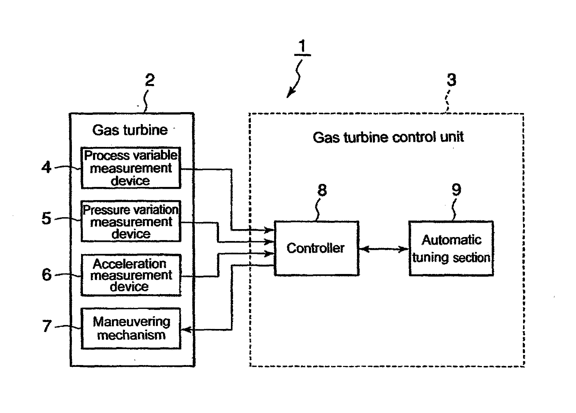
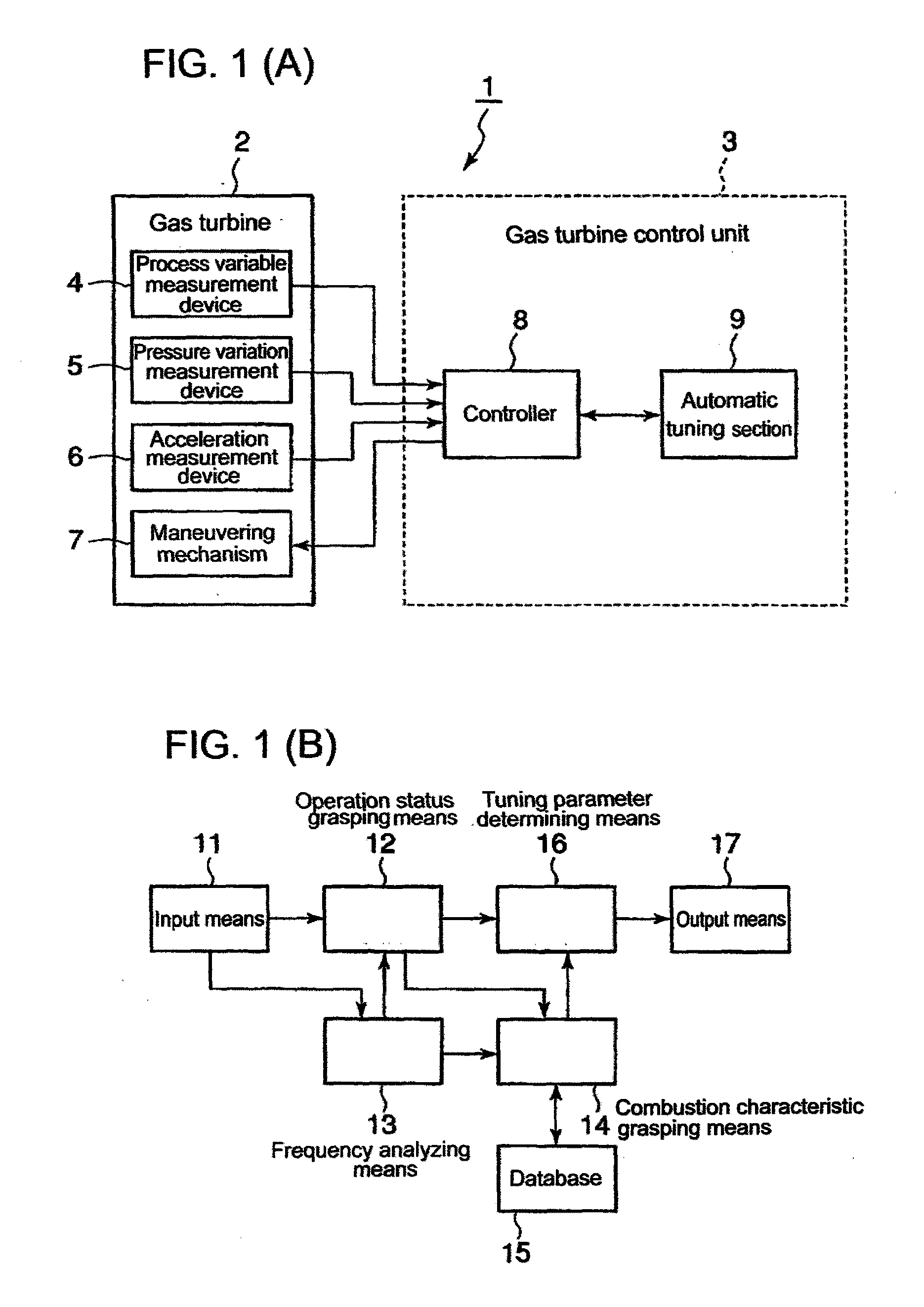
[0097]In the first place, a gas turbine 2 is briefly explained in relation to FIG. 10 that shows the configuration of the gas turbine 2 as well as FIG. 11 that shows the outline cross section as to the configuration of the combustor 23 of the gas turbine 2. At first, as shown in the outline cross-section of FIG. 10, the gas turbine comprises: a compressor 22 having a plurality of inlet guide vanes 26; a gas-turbine body 21 having a turbine 24 connected to the compressor 22 and a generator 40, via a rotating shaft 39, thereby a combustor 23 supplies the combustion gas to the turbine 24 through a combustion gas introduction tube 38, and the combustion gas is discharged outside through a piping system.

[0098]The rotational movement of the turbine 24 is transferred to the rotational movement of the compressor 22 through the a rotating shaft 39; the compressor inhales the ambient air 25 through an air suction port that is fitted at the compressor and provided with a filter; the compressor...

second embodiment

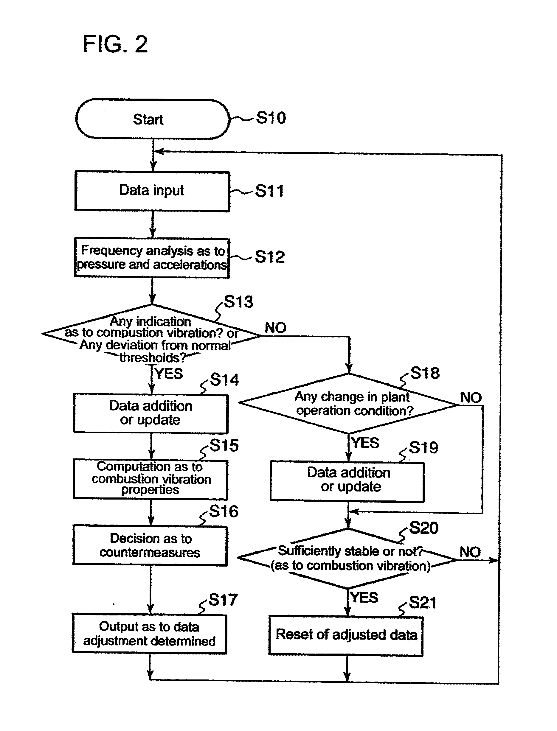
[0160]Thus far, the explanation has been given about the first embodiment whereby the reset practice is incorporated so that adjusted variables return back to the initial condition, in a case where the gas turbine operation is performed at an operating point deviating from a regular operation point that is determined at the design stage of the gas turbine based on the assumed ideal fuel flow rate or air flow rate to satisfy design performance requirements. In this approach, however, a deterioration factor such as a gas turbine life consuming deterioration is not taken into consideration; thus, the operation variables (i.e. actuating variables) return back to the initial settings thereof, even when the current operation point deviates from the initial ideal operation point due to the life consuming or aging of the gas turbine 2. Hence, in the following second embodiment of this invention, the adjustment approach to solve this problem is disclosed.

[0161]FIG. 3 shows a flow diagram as ...


PUM


Abstract

A gas turbine control method for preventing then operation from deviating from the operating state at the ideal fuel and air flow-rates expected when the gas turbine is designed and maintaining an efficient operating state. A gas turbine control device comprises a frequency analyzing means for analyzing the frequencies inside the combustor of a gas turbine, a state grasping means for grasping the combustion state in the gas turbine on the basis of a state signal representing the result of the analysis by frequency band, the amount of operation process including a ratio between the air flow rate and pilot fuel in the gas turbine, the atmosphere state, and the load amount, a combustion characteristic grasping means for grasping the characteristic of the combustion vibration, and a control section for calculating a correction value of at least either the air flow rate supplied to the combustor or the pilot ratio from the grasped combustion vibration characteristic and the grasped combustion state each time the degree of the combustion vibration exceeds a predetermined control value, correcting the initial design values of the air flow rate and the pilot ratio predetermined correspondingly to the amount of operation process and the state signal, and thereby driving the gas turbine. The control section resets the correction of the initial design values when the degree of combustion vibration of the gas turbine is below the predetermined control value for a given period of time and operates the gas turbine using the initial design values.

Description

BACKGROUND OF THE INVENTION[0001]1. Field of the Invention[0002]The present invention relates to a control method and a control device as to a gas turbine; More concretely, the present invention relates to a gas turbine control method and a control device thereof for controlling the gas turbine so that the gas turbine is prevented from continuing an operation out of the regular operation line (condition), namely an operation line under an ideal fuel flow rate and air flow rate that are assumed at the design stage of the gas turbine, by adjusting operation control factors so as to restrain the combustion vibrations during the operation of the gas turbine.[0003]2. Background of the Invention[0004]For instance, in a gas turbine driving a generator (an AC generator), the air flow rate and the fuel flow rate toward the combustors of the gas turbine are determined based on the load (the power required by the generator), the ambient temperature, the ambient humidity and so on; and the air ...

Claims


Application Information

Patent Timeline
IPC IPC(8): F02C9/50
CPCF02C9/52F02C9/28F02C9/54F05D2270/114F05D2270/14F05D2270/301F05D2270/3061F05D2270/332F05D2270/334
Inventor NOMURA, MASUMIMIYAUCHI, KOTARO
Owner MITSUBISHI POWER LTD
Why Eureka
Try Eureka