Encapsulated Solar Cell

a solar cell and solar cell technology, applied in photovoltaics, sustainable buildings, electrical equipment, etc., can solve the problems of solar cell rust and possible corrosion of antireflection coatings, and achieve the effect of preventing air pockets and cost-effective production

Inactive Publication Date: 2010-08-12
BLUENERGY
View PDF8 Cites 14 Cited by
  • Summary
  • Abstract
  • Description
  • Claims
  • Application Information

AI Technical Summary

Benefits of technology

[0050]Preferably, in the combination of the fluoropolymer and silicon film for embedding solar cells the surfaces of the fluoropolymer films are adjusted such that the tough-structured surface makes them abrasion-resistant and that sand storms cannot cause any destruction.
[0051]Preferably, e.g. pyramid structures, roll laminations (nearly continuous production) can be realized in the combination of fluoropolymer and silicon film for embedding solar cells due to a rough surface with ducts that permit suctioning off air. Normally, photovoltaic modules are produced in vacuum chambers in that the vacuum first suctions off the air between the laminating films and the solar cells, followed by heating and pressing the composite together. This process step is costly and requires a lot of energy. The air can be continuously suctioned off and squeezed out during roll compressing (e.g., roll lamination) through the thermoelastic silicon film with pyramid-like surface structure, so that air pockets are prevented. This makes a more cost-effective production possible.

Problems solved by technology

This leads to a silvering of the solar cells.
Any antireflection coating possibly present is also corroded thereby.

Method used


Image

  • Encapsulated Solar Cell
  • Encapsulated Solar Cell
  • Encapsulated Solar Cell

Examples


Embodiment Construction

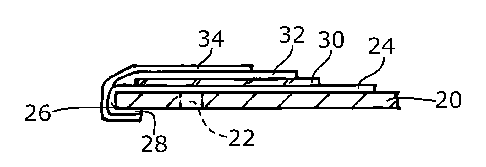
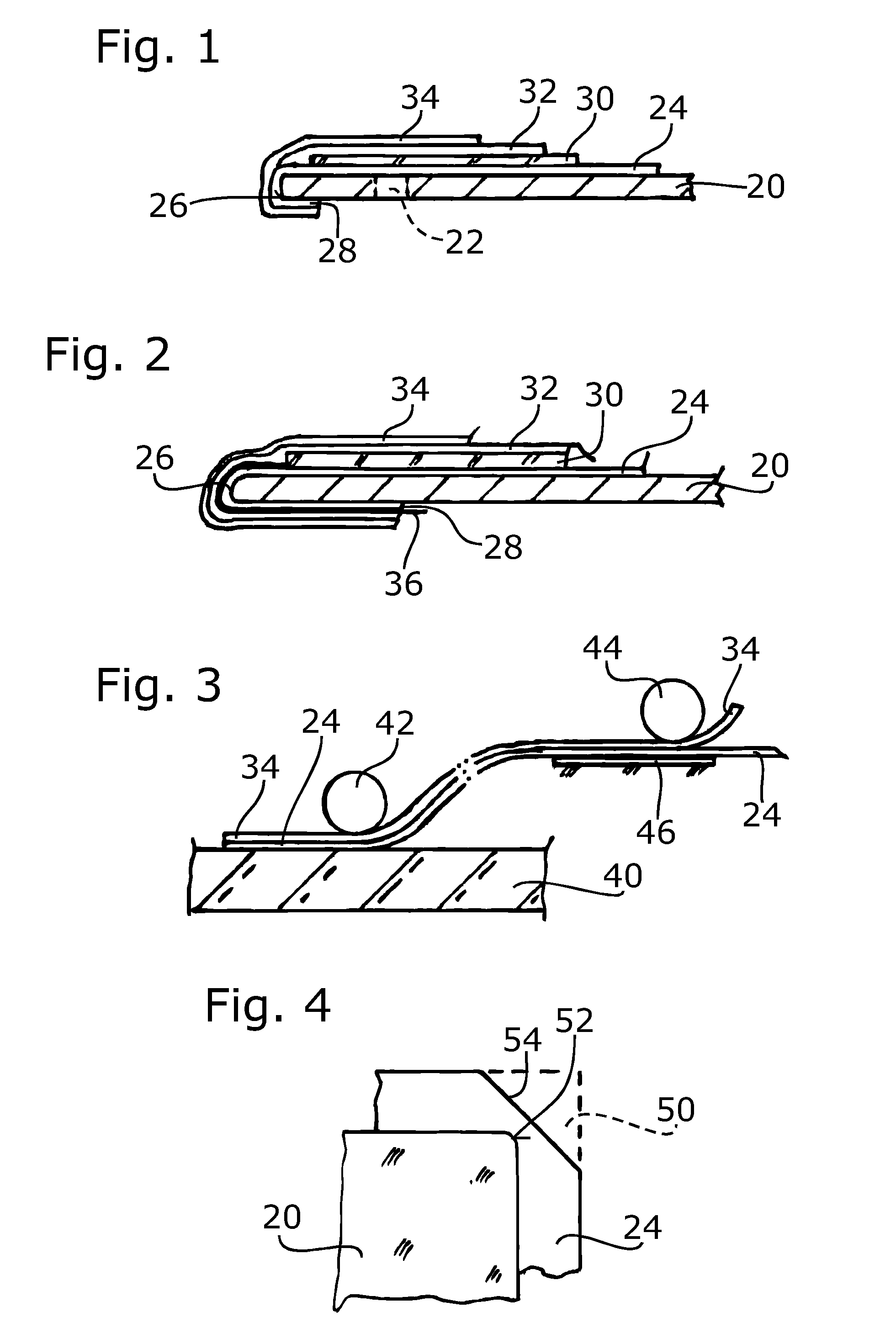
[0063]The encapsulated solar cell shown in FIG. 1 has a substrate 20, which is for example an aluminum sheet; it may have openings 22, through which the material of the layers comprised of thermoplastic silicon can flow.

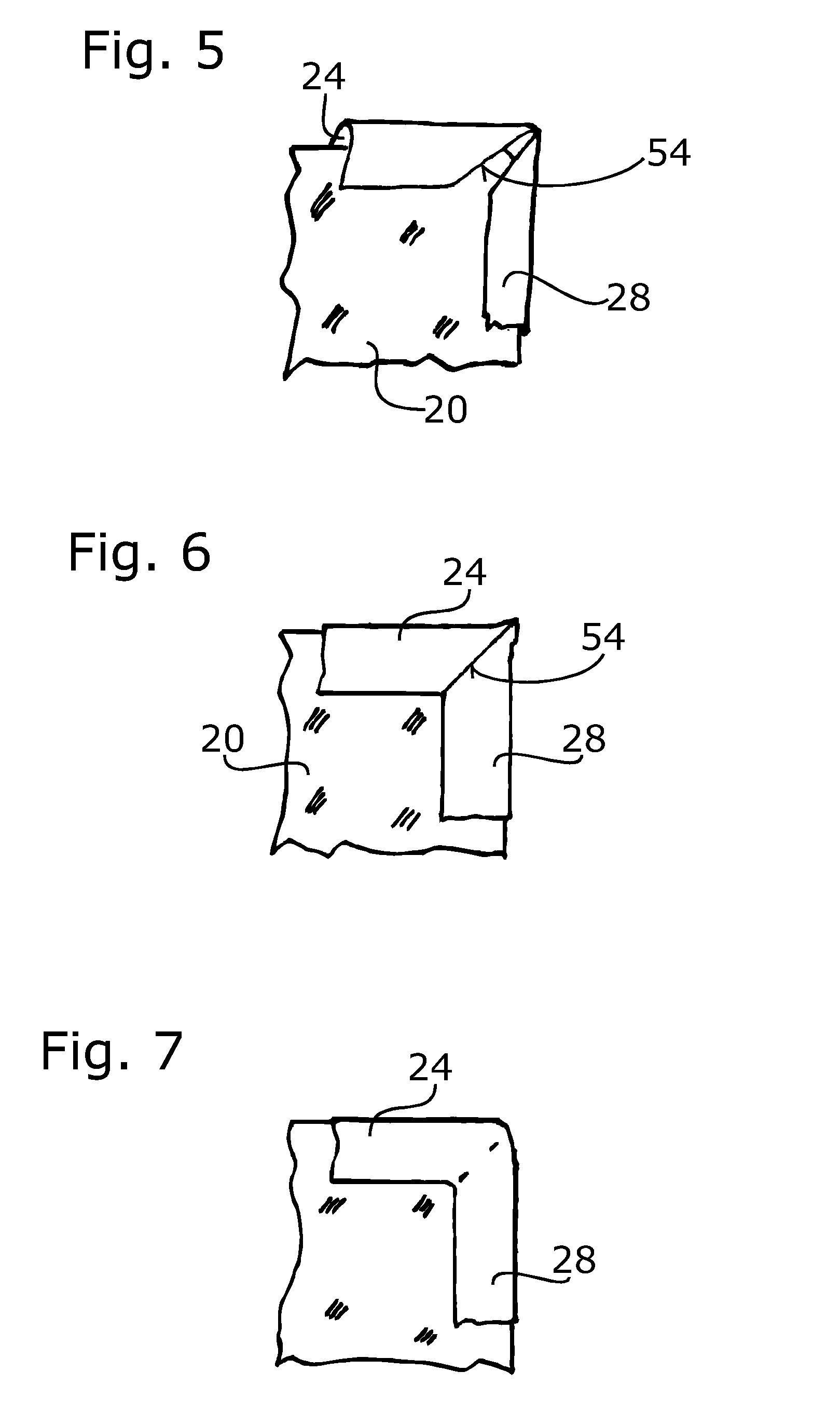
[0064]A lower layer 24 comprised of thermoplastic silicon, which is approximately 500 μm thick, is located on the upper main surface of the substrate 20. As shown in FIG. 1, the surface area of this lower layer 24 is larger than the substrate 20. It is wrapped around the edges 26 of the substrate and abuts with its end regions 28 the undersurface of the substrate 20. The contact between the lower layer 24 and the substrate 20 is bubble-free. A bond has been achieved there.

[0065]A solar cell 30 is applied to the lower layer 24. This involves a state-of-the-art solar cell. Its surface area can be slightly smaller than the substrate 20, it can, however, virtually also be as large as that of the substrate 20. An upper layer 32 is applied onto this solar cell 30 and to th...


PUM

PropertyMeasurementUnit
thicknessaaaaaaaaaa
thickaaaaaaaaaa
thickaaaaaaaaaa

Abstract

The present invention relates to an encapsulated solar cell having the following layer structure: a lower layer of thermoplastic silicone; a solar cell; an upper layer of thermoplastic silicone; a cover layer of a fluoropolymer, wherein the solar cell is sealed all around between the lower layer and the upper layer and wherein the upper layer is bonded to the cover layer.

Description

CROSS-REFERENCE TO PRIORITY APPLICATIONS[0001]This application is a continuation of pending International Application No. PCT EP2008 / 064086 (filed Oct. 20, 2008, and published Apr. 30, 2009, as Publication No. WO 2009 / 053321 A2,) which itself claims the benefit of commonly assigned German Application Serial No. 10 2008 045 997.6 (filed Sep. 5, 2008), and commonly assigned German Application Serial No. 10 2007 050 964.4 (filed Oct. 23, 2007). This application hereby claims the benefit of and incorporates entirely by reference International Application No. PCT EP2008 / 064086, German Patent Application Serial No. 10 2008 045 997.6, and German Patent Application Serial No. 10 2007 050 964.4.FIELD OF THE INVENTION[0002]The invention relates to an encapsulated solar cell as well as to a method for producing an encapsulated solar cell of this type. Encapsulated solar cells of this type and corresponding methods for the production thereof are generally known, reference is made merely by way ...

Claims


Application Information

Patent Timeline
Patent Type & Authority Applications(United States)
IPC IPC(8): H01L31/0203H01L31/18
CPCB29C63/04B32B25/08B32B25/14B32B27/08H02S20/23B32B37/04B32B2457/12Y02B10/12B32B37/003Y02B10/10Y02E10/50
Inventor MELCHIOR, BERND
Owner BLUENERGY
Why Eureka
Try Eureka