High-resolution optical code imaging using a color imager

a color imager and high-resolution technology, applied in the field of data reading systems and methods, can solve the problem that the reader cannot achieve effective high-resolution optical resolution comparable, and achieve the effect of improving the optical reading devi

Active Publication Date: 2010-08-12
DATALOGIC ADC
View PDF29 Cites 63 Cited by
  • Summary
  • Abstract
  • Description
  • Claims
  • Application Information

AI Technical Summary

Benefits of technology

[0007]This disclosure describes improved optical reading devices and associated methods.

Problems solved by technology

Some image-based readers have included color imagers, but the present inventors have recognized that those readers do not effectively achieve high optical resolution comparable to monochrome image-based readers with the same number and size of pixels.

Method used


Image

  • High-resolution optical code imaging using a color imager
  • High-resolution optical code imaging using a color imager
  • High-resolution optical code imaging using a color imager

Examples


first embodiment

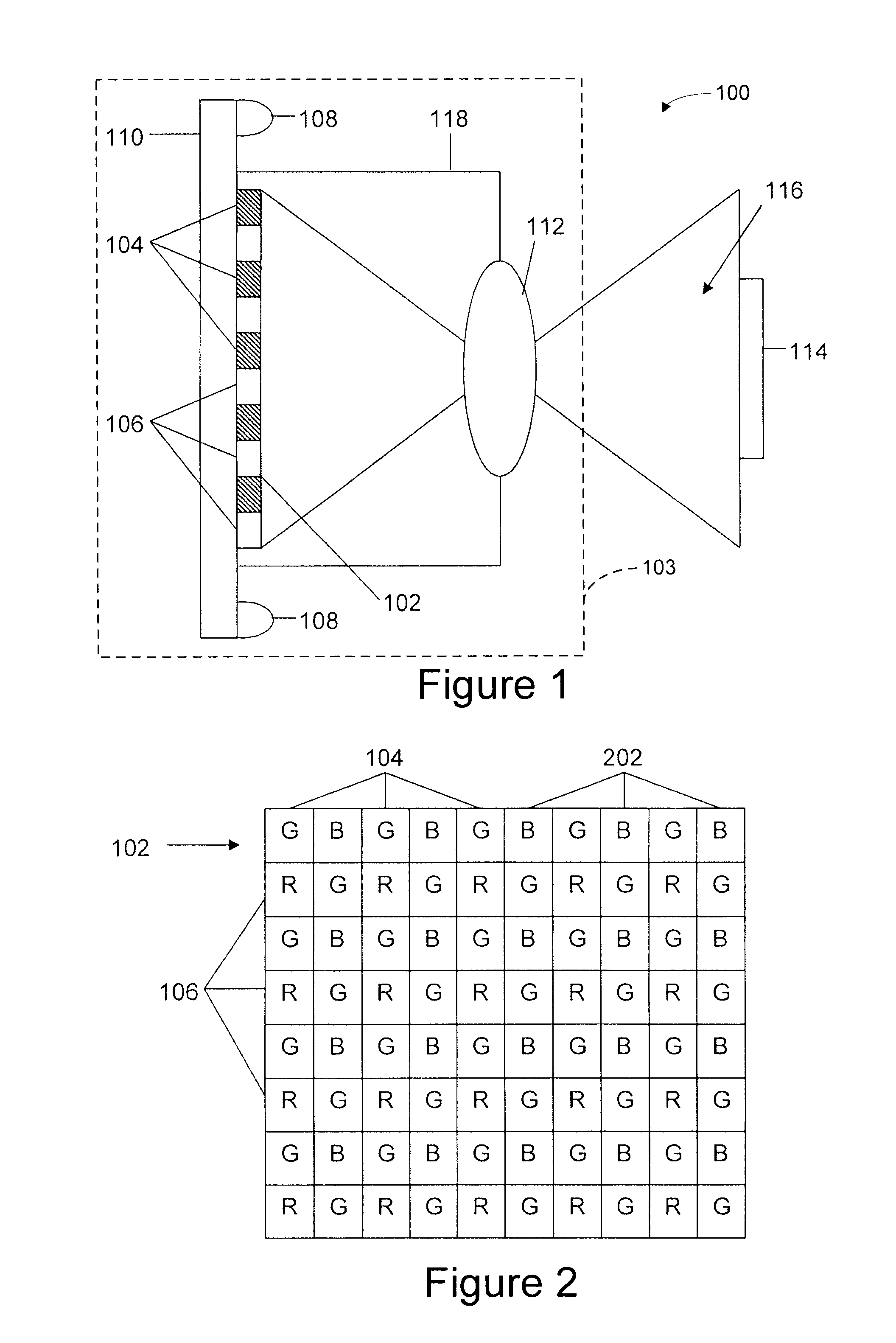
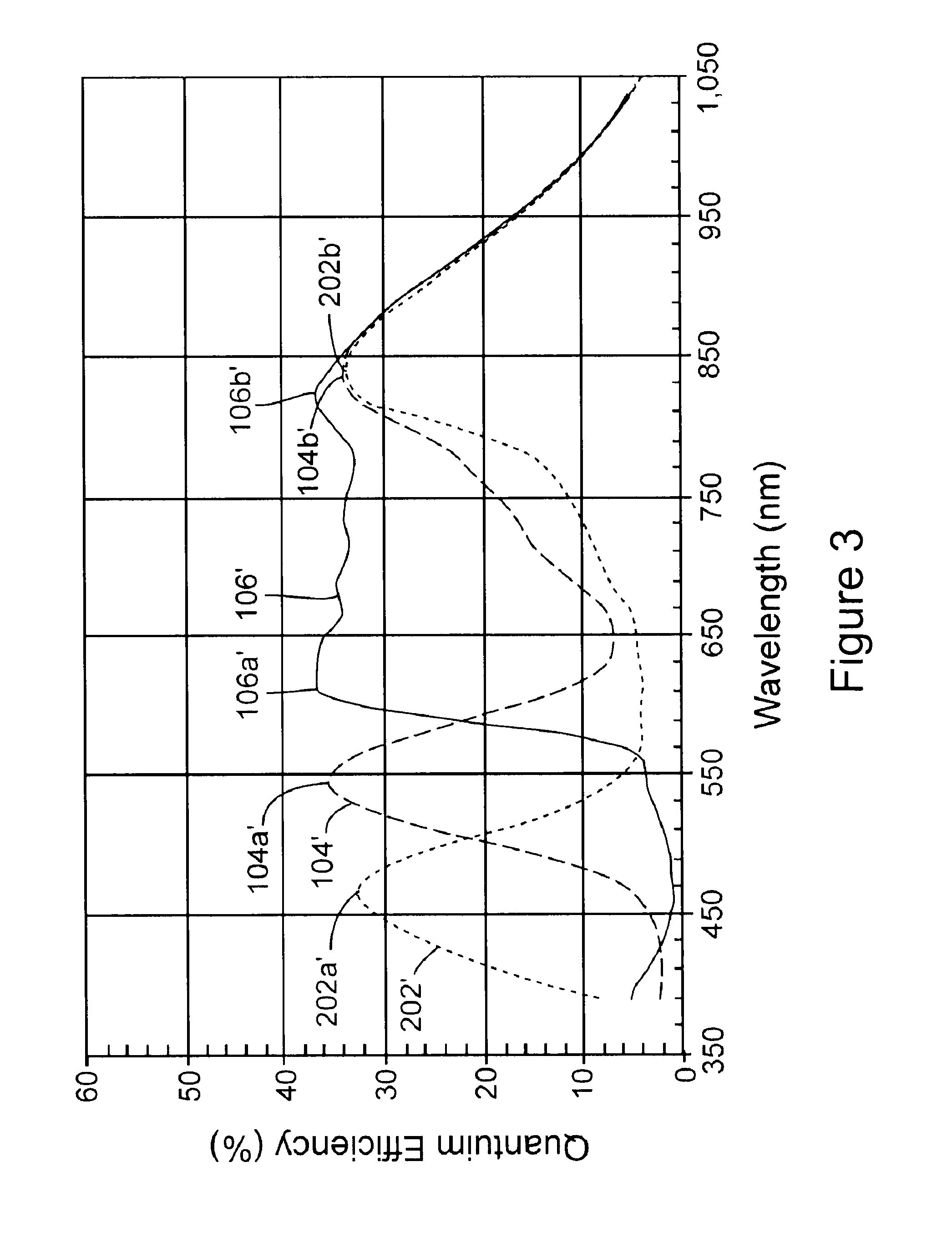
[0020]The imaging device 100 may also include one or more artificial illumination sources 108 (two illumination sources are depicted in FIG. 1). The artificial illumination sources 108 may be mounted to a printed circuit board 110 upon which the color image sensor array 102 is also mounted. In a first embodiment, the artificial illumination sources 108 are operable to emit infrared illumination. The infrared illumination emitted by the artificial illumination sources 108 may be narrowband infrared illumination (e.g., illumination having a bandwidth less than about 100 nm). Also, the wavelength bandwidth of light emitted by the artificial illumination sources 108 preferably includes 850 nm, when using a color image sensor array with characteristics shown in FIG. 3.

[0021]The imaging device 100 typically includes a suitable optical system 112 positioned to focus light upon the color image sensor array 102. The optical system 112 may include conventional optical components, such as one ...

third embodiment

[0028]One of several different methods may be used for comparing the sharpness of the color planes. For example, techniques used in passive auto-focusing systems may be used. As additional examples, the amount of high spatial frequency content of the color planes may be measured (such as by computing a Fourier transform), or edge sharpness for the color planes may be measured (i.e., measuring the intensity difference between neighboring pixels). By knowing which color plane is in best focus, and by knowing the depth of field associated with the best focused color plane, distance between the object 114 and the imaging device 100 may be estimated. Distance estimation using an optical code reading device may be useful in a number of applications. For example, estimating distance may be used for measuring the dimensions of an optical code to ascertain whether the optical code is of acceptable size (i.e., whether the optical code was printed properly). The third embodiment also provides ...


PUM


Abstract

An optical code or other data reading device includes a color image sensor array positioned to sense light reflected from an object, and to produce image data. In one configuration, the color image sensor array has multiple sets (e.g., first and second sets) of sensor elements that are sensitive to corresponding visible wavelength bands of light (e.g., first and second wavelength bands), the sets also being sensitive to light within an infrared wavelength band. An artificial illumination source is positioned to illuminate the field of view with light that is reflected off an object in the field of view toward the image sensor array, the illumination source being operable to produce infrared light having wavelengths within the infrared wavelength band so that, upon illumination, at least some sensor elements of each of the sets are sensitive to the infrared light and contribute to production of the image data.

Description

RELATED APPLICATION[0001]This application claims benefit under 35 U.S.C. §119(e) of U.S. Provisional Application No. 61 / 151,768, titled “High-Resolution Optical Code Imaging Using a Color Imager,” filed Feb. 11, 2009, the entire contents of which is incorporated herein by reference.TECHNICAL FIELD[0002]The field of this disclosure relates generally to systems and methods of data reading, and more particularly but not exclusively to reading of optical codes (e.g., bar codes).BACKGROUND INFORMATION[0003]Optical codes encode useful, optically-readable information about the items to which they are attached or otherwise associated. Perhaps the most common example of an optical code is the bar code. Bar codes are ubiquitously found on or associated with objects of various types, such as the packaging of retail, wholesale, and inventory goods; retail product presentation fixtures (e.g., shelves); goods undergoing manufacturing; personal or company assets; and documents. By encoding informa...

Claims


Application Information

Patent Timeline
Patent Type & Authority Applications(United States)
IPC IPC(8): G06K7/12G06K7/10
CPCG06K7/10722G06K7/10732G06K7/12
Inventor OLMSTEAD, BRYAN L.SHEARIN, ALAN
Owner DATALOGIC ADC
Why Eureka
Try Eureka