Wireless radio frequency signal transceiving system

a radio frequency signal and transceiving system technology, applied in the field of wireless transceiving system, can solve the problems of data transmission therebetween, limited hardware device use, and restricted transmission bandwidth

Active Publication Date: 2010-08-12
NAT TAIWAN UNIV
View PDF5 Cites 84 Cited by
  • Summary
  • Abstract
  • Description
  • Claims
  • Application Information

AI Technical Summary

Problems solved by technology

Data transmission therebetween, is therefore limited by the hardware devices used and restricted transmission bandwidths.

Method used


Image

  • Wireless radio frequency signal transceiving system
  • Wireless radio frequency signal transceiving system
  • Wireless radio frequency signal transceiving system

Examples


Embodiment Construction

[0023]The following description is of the best-contemplated mode of carrying out the invention. This description is made for the purpose of illustrating the general principles of the invention and should not be taken in a limiting sense. The scope of the invention is best determined by reference to the appended claims.

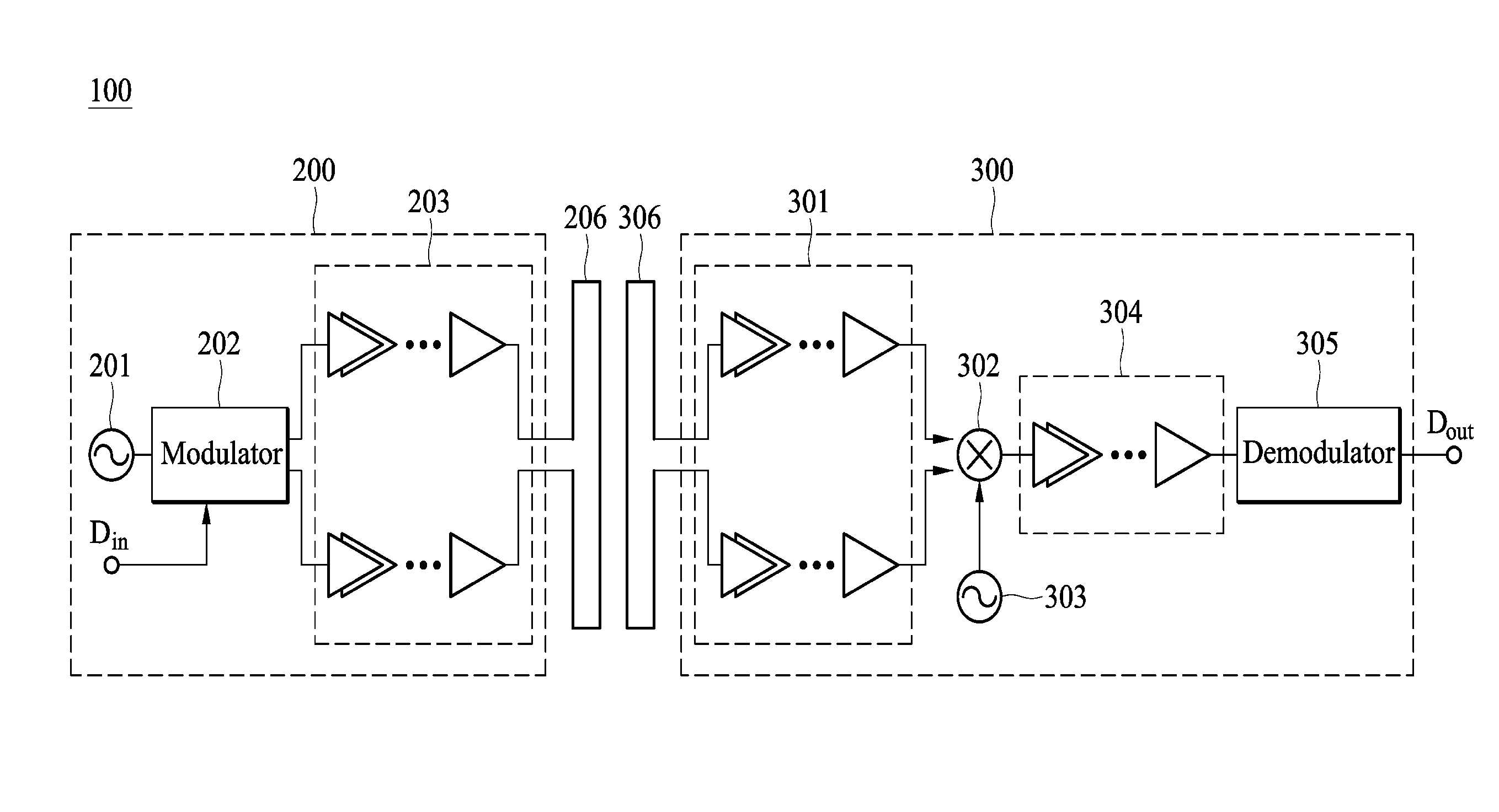
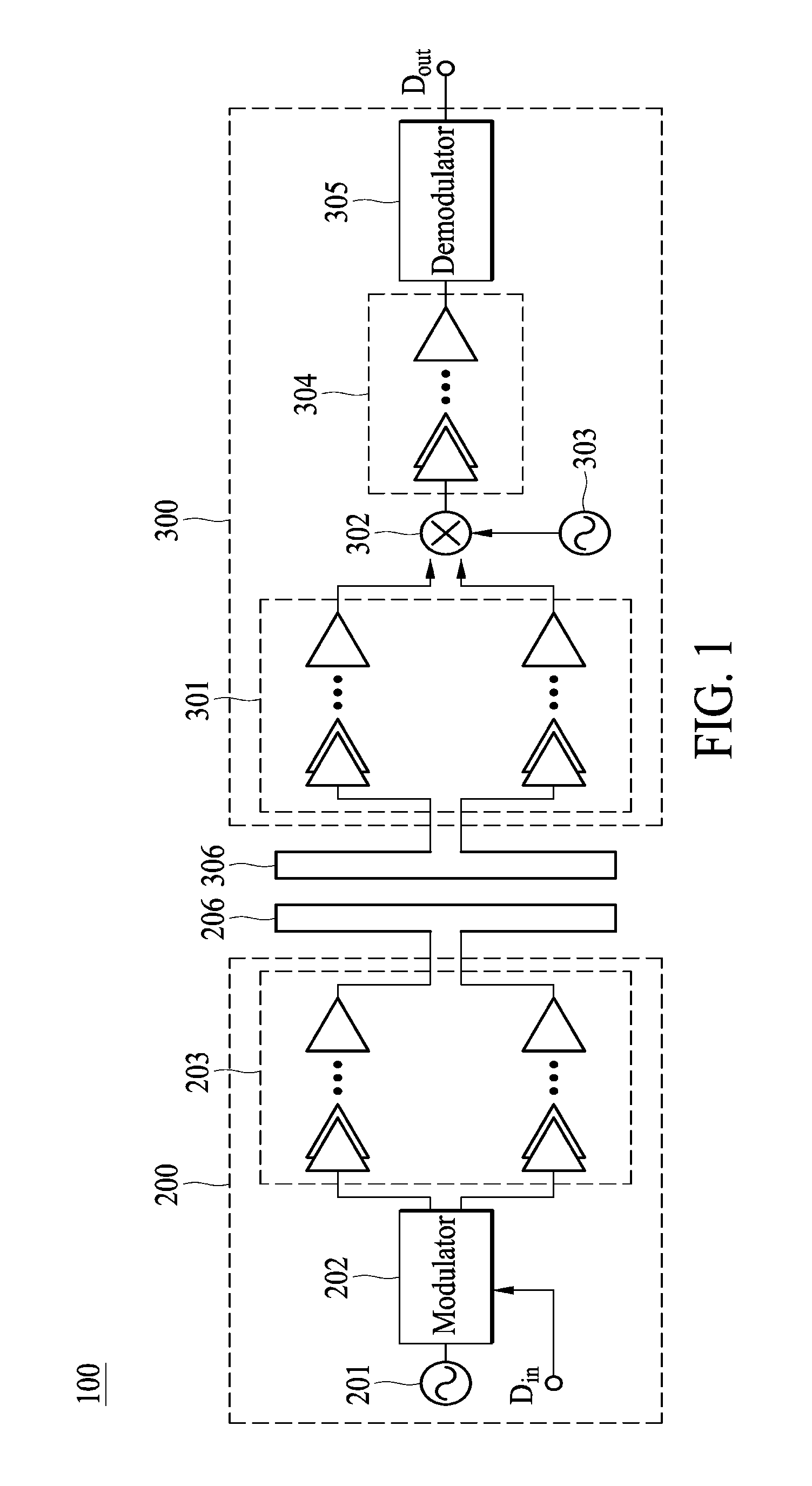
[0024]According to an embodiment of the invention, a high speed wireless radio frequency signal transceiving system with 60 GHz carrier frequency is provided. The frequency band around 60 GHz is a license free region for commercial or populace use. Compared with the conventional 2.4 GHz frequency band, the 60 GHz may be used with a wider bandwidth (achieving a bandwidth width of 7 GHz). Thus, data transmissions with much higher speeds (i.e. data rate) may be realized. However, it is difficult to design a transceiving system to operate at an extremely high frequency such as 60 GHz. Thus, according to an embodiment of the invention, a novel modulation scheme is provided ...


PUM


Abstract

A differential radio frequency signal transmitter is provided. The differential radio frequency signal transmitter includes an oscillator, a modulator and an amplifier module. The oscillator generates a pair of differential oscillation signals. The modulator generates a pair of differential modulated signals according to an input signal and the pair of differential oscillation signals. The input signal is a digital signal. When the input signal is at a first state, the modulator outputs the pair of differential oscillation signals as the pair of differential modulated signals, and when the input signal is at a second state, the modulator outputs a constant voltage signal as the pair of differential modulated signals. The amplifier module receives and amplifies the pair of differential modulated signals and generates a pair of differential radio frequency signals, accordingly.

Description

CROSS REFERENCE TO RELATED APPLICATIONS[0001]This Application claims priority of Taiwan Application No. 98103811, filed on Feb. 6, 2009, the entirety of which is incorporated by reference herein.BACKGROUND OF THE INVENTION[0002]1. Field of the Invention[0003]The invention relates to a wireless transceiving system, and more particularly to a high speed wireless transceiving system.[0004]2. Description of the Related Art[0005]Along with advancements in technology, electronic consumer products, such as the digital cameras, digital video recorders, mobile phones, personal digital assistants (PDA), Universal Serial Bus (USB) storage disks, and personal computers, among others, have been rapidly developed. Electronic consumer products usually include a memory to store data required by the system operations or the data set or recorded by the user. However, for conventional designs, a wired transmission line, such as a USB transmission line, a High Definition Multimedia Interface (HDMI) tra...

Claims


Application Information

Patent Timeline
Patent Type & Authority Applications(United States)
IPC IPC(8): H04B1/38H04L27/00H04L25/06
CPCH03D7/1441H03F1/223H01L2924/3011H01L2924/30107H01L2224/49113H01L2224/49109H01L2224/48091H03F1/565H03F3/195H03F3/45183H03F3/45892H03F2200/222H03F2200/294H03F2200/318H03F2200/375H03F2200/387H03F2203/45638H03F2203/45641H03F2203/45644H03F2203/45646H03F2203/45652H03F2203/45702H03F2203/45726H03F2203/45728H04L27/201H03D7/1483H03D2200/0025H03D2200/0043H03D2200/0047H01L24/49H01L2924/00014H01L2924/00H01L2924/30111H01L24/48H01L2224/45099H01L2224/05599
Inventor LEE, JR-IHUANG, YEN-LINCHEN, YEN-TSOCHANG
Owner NAT TAIWAN UNIV
Why Eureka
Try Eureka