Centrifugal fan

a centrifugal fan and fan body technology, applied in the direction of liquid fuel engines, vessel construction, marine propulsion, etc., can solve the problems of deteriorating the original performance of each blade, and achieve the effect of reducing air turbulence, intense energy, and effective reducing fan nois

Active Publication Date: 2010-08-12
DAIKIN IND LTD
View PDF8 Cites 24 Cited by
  • Summary
  • Abstract
  • Description
  • Claims
  • Application Information

AI Technical Summary

Benefits of technology

[0022]In the above centrifugal fan, it is preferable that each blade have a leading edge and a trailing edge, that the blade be arranged with the leading edge facing the center of the main plate and the trailing edge facing the outer periphery of the main plate, and that the trailing edge of the blade is formed in a sawtooth-like shape. This decreases the air turbulence caused by the airflows moving along the two surfaces of each blade and converging, thus effectively reducing the fan noise.
[0023]In the above centrifugal fan, it is preferable that each blade have a leading edge and a trailing edge, that the blade be arranged with the leading edge facing the center of the main plate and the trailing edge facing the outer periphery of the main plate, and that a portion of the leading edge of the blade close to the main plate be formed in a stepped shape. In this case, the airflow moving toward the leading edge of each blade becomes turbulent by hitting the discontinuous portion formed by the stepped portion. A vertical vortex in the drawn air is thus guided by the stepped surface of the stepped portion and generated in a concentrated manner on an outer peripheral surface or an inner peripheral surface of the blade. As a result, the vertical vortex develops and produces an intense energy. The thus formed vertical vortex effectively suppresses separation of an airflow produced on the outer peripheral surface or the inner peripheral surface of the blade. Accordingly, the fan noise is reliably reduced.
[0024]In the above centrifugal fan, it is preferable that each blade have a horseshoe vortex suppressing portion, that the horseshoe vortex suppressing portion be formed by curving a portion of the leading edge of the blade close to the main plate such that the portion projects in the rotating direction. In this case, the joint portion between the leading edge of each blade and the main plate is asymmetrical. This suppresses a horseshoe vortex generated at the joint portion between the main plate and the blade. Accordingly, the influence on the airflow flowing along the blade is reduced, and the air blowing performance is effectively improved.
[0025]In the above centrifugal fan, it is preferable that each blade have a horseshoe vortex suppressing portion, and that the horseshoe vortex suppressing portion be formed by curving a portion of the leading edge of the blade close to the main plate such that the portion projects in the direction opposite to the rotating direction. In this case, the joint portion between the leading edge of each blade and the main plate is asymmetrical. This suppresses a horseshoe vortex generated at the joint portion between the main plate and the blade. Accordingly, the influence on the airflow flowing along the blade is reduced, and the air blowing performance is effectively improved.
[0026]In the above centrifugal fan, it is preferable that each blade have a forward-swept blade structure, and that the forward-swept blade structure be formed by projecting a portion of the leading edge of the blade close to the main plate toward the center of the main plate. In this case, pressing force is applied from the main flow of drawn airflows to the main plate at the leading edge of each blade. This either makes it difficult for a horseshoe vortex to generate or reduces the size of the horseshoe vortex, in a synergetic manner with the action brought about by the bent structure. As a result, the influence on the airflow moving along each blade is decreased, and the air blowing performance is further effectively improved.
[0027]In the above centrifugal fan, it is preferable that each blade have a retreating blade structure, and that the retreating blade structure be formed by recessing a portion of the leading edge of the blade close to the main plate. In this case, at the leading edge of each blade, pressing force is applied from a main airflow, the speed of which has been increased after the air has been drawn, to the main plate. This either makes it difficult for a horseshoe vortex to generate or reduces the size of the horseshoe vortex. As a result, the influence on the airflow moving along each blade is decreased, and the air blowing performance is further effectively improved.

Problems solved by technology

This deteriorates the original performance of each blade 16.

Method used


Image

  • Centrifugal fan
  • Centrifugal fan
  • Centrifugal fan

Examples


first embodiment

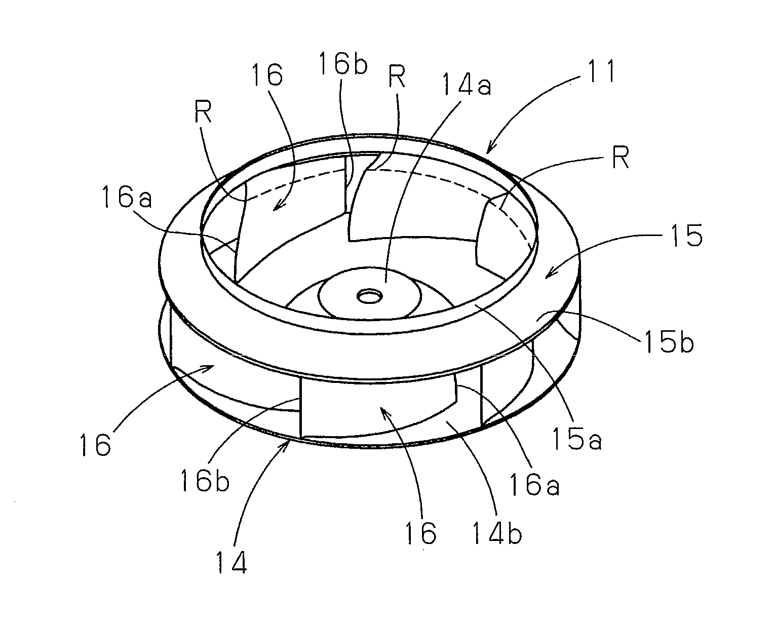
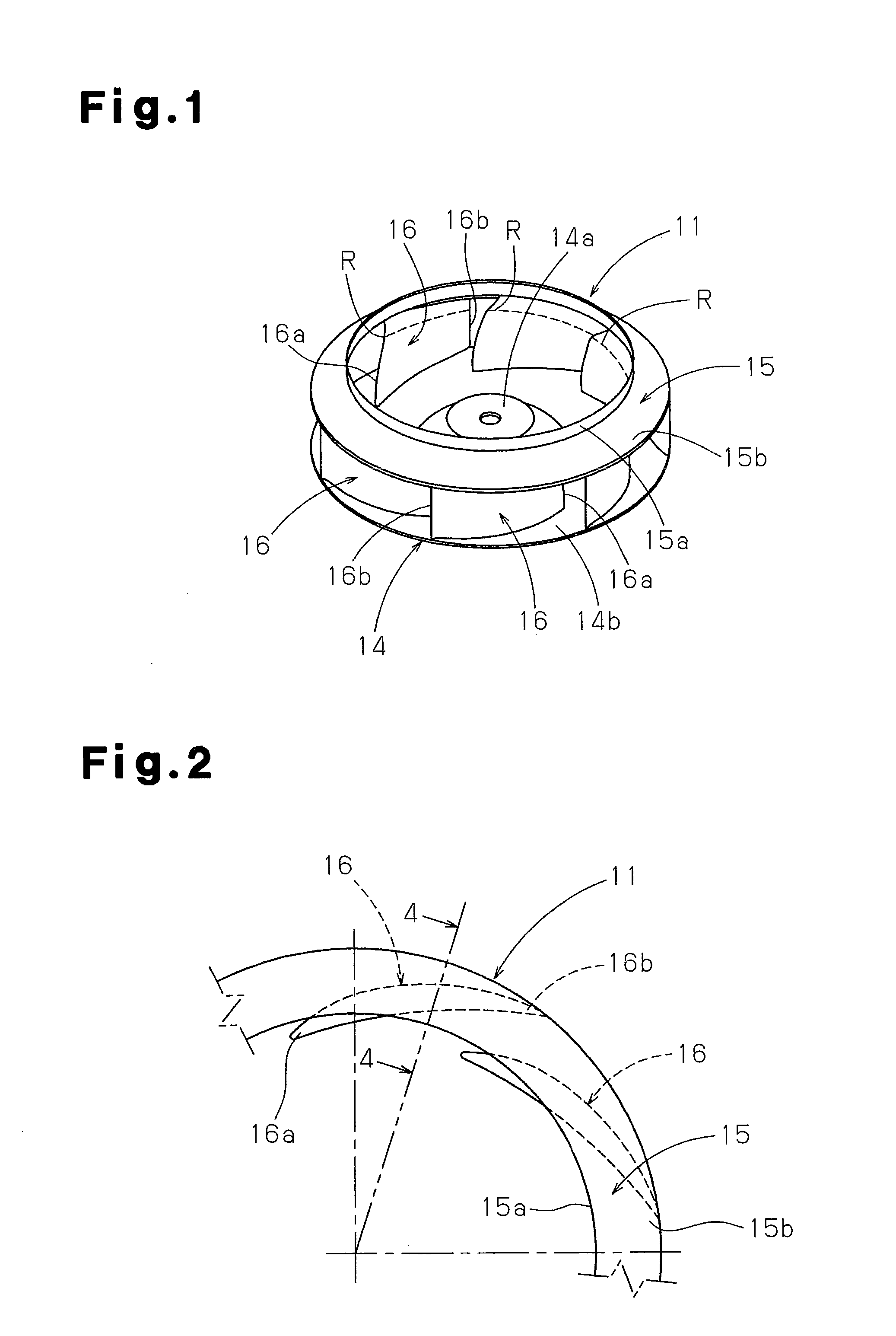
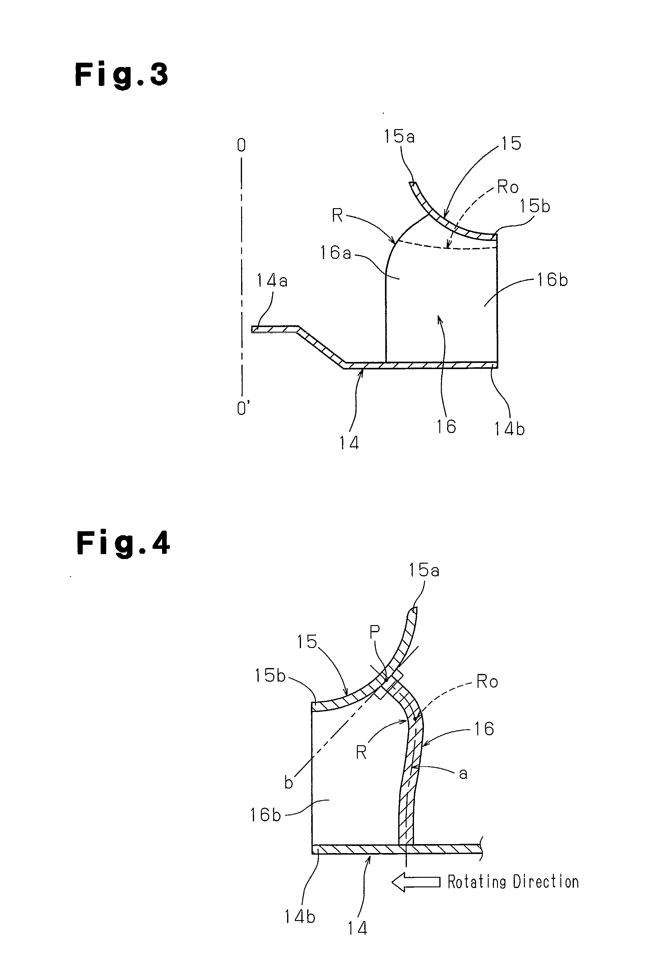
[0065]A centrifugal fan (a turbofan) according to a first embodiment of the present invention, which is employed in an indoor unit of a ceiling embedded air conditioner, will be explained with reference to FIGS. 1 to 5.

[0066]As illustrated in FIGS. 1 to 3, a centrifugal fan (a turbofan) 11 has a circular main plate (a hub) 14, a tubular side plate (a shroud) 15, and a plurality of blades (rotor blades) 16, which are arranged between the main plate 14 and the side plate 15. The main plate 14 is fixed to a rotary drive shaft 13a of a fan motor 13 illustrated in FIG. 31. The blades 16 are arranged at predetermined blade angles and spaced apart at predetermined intervals in the circumferential direction. The side plate 15 has two opening ends having different outer diameters. One of the opening ends of the side plate 15 forms an air inlet port, which guides air in centrifugal directions in an impeller. An air outlet port portion 6c of a bellmouth 6 is loosely received in an air inlet en...

second embodiment

[0075]A centrifugal fan according to a second embodiment of the present invention, which is used in an indoor unit of a ceiling embedded air conditioner, will now be described with reference to FIGS. 6 to 10.

[0076]As illustrated in FIGS. 6 to 10, the second embodiment has an additional curved portion formed close to the joint portion between each blade 16 and the main plate 14 of the centrifugal fan according to the first embodiment. This suppresses a horseshoe vortex produced on each surface of the blade 16 at the joint portion between the blade 16 and the main plate 14.

[0077]With reference to FIGS. 36 to 38, when each blade 16 extends perpendicular to the flat main plate 14 as in the case of the first embodiment illustrated in FIGS. 1 to 5, a horseshoe vortex is produced around the position at which the main plate 14 and the leading edge 16a of the blade 16 cross each other. As the horseshoe vortex is generated and increased, the original airflow moving along the blade 16 is inter...

third embodiment

[0081]A centrifugal fan according to a third embodiment of the present invention, which is employed in an indoor unit of a ceiling embedded air conditioner, will hereafter be described with reference to FIG. 12.

[0082]As illustrated in FIG. 12, the third embodiment is characterized in that a horseshoe vortex suppressing portion, which is similar to that of the second embodiment, is formed by a forward-swept blade structure S. The forward-swept blade structure S is formed by projecting a portion of the leading edge 16a of each blade 16 close to the main plate 14 toward the center of the main plate 14 by a predetermined dimension.

[0083]In this configuration, as represented by the arrows of phantom lines in FIG. 12, a drawn airflow (a main airflow) applies pressing force to both surfaces of each blade 16 at the joint portion between the leading edge 16a of the blade 16 and the main plate 14. This either makes it difficult for a horseshoe vortex to be generated or reduces the size of the...


PUM


Abstract

A centrifugal fan has a circular main plate driven and rotated by a motor rotary shaft, a plurality of blades fixed to an outer circumferential portion of the main plate and spaced apart at predetermined intervals in a circumferential direction of the main plate, and a side plate attached to ends of the blades opposite to the main plate. An air inlet port is formed at the center of the side plate. The side plate inclines outward in centrifugal directions from the air inlet port and has an arcuate cross section with a predetermined radius of curvature. A dead water region reducing space is formed between the blades and the side plate. The dead water region reducing space forms a smooth flow between the two surfaces of each blade, bringing about desirable blade performance.

Description

TECHNICAL FIELD[0001]The present invention relates to the structure of a centrifugal fan.BACKGROUND ART[0002]Patent Document 1, for example, discloses a centrifugal fan such as a turbofan having a plurality of blades, which are arranged between a main plate and a side plate (a shroud). FIGS. 31 to 34 each illustrate a turbofan employed in the indoor unit of a ceiling embedded air conditioner.[0003]With reference to FIGS. 31 to 34, an indoor unit 1 of a ceiling embedded air conditioner has a cassette type body casing 2, which is embedded in a ceiling 3. An air inlet / outlet panel 4 is arranged at a lower surface of the body casing 2. The air inlet / outlet panel 4 is substantially flush with the ceiling 3.[0004]A rectangular air inlet grill 5 is arranged at the center of the air inlet / outlet panel 4. A bellmouth 6 of a turbofan 11 is arranged at the backside of the air inlet grill 5 in the body casing 2. A plurality of air outlet ports 9 each having a predetermined width are formed in t...

Claims


Application Information

Patent Timeline
Patent Type & Authority Applications(United States)
IPC IPC(8): F04D29/28
CPCF04D29/282F04D29/30
Inventor IWATA, TORUZHENG, ZHIMING
Owner DAIKIN IND LTD
Why Eureka
Try Eureka