

Integrated system design
- Summary
- Abstract
- Description
- Claims
- Application Information
AI Technical Summary
Benefits of technology
Problems solved by technology
Method used
Image

Examples
Embodiment Construction
[0020]In the following description, reference is made to the accompanying drawings which form a part hereof, and which is shown, by way of illustration, several embodiments of the present invention. It is understood that other embodiments may be utilized and structural changes may be made without departing from the scope of the present invention.
Hardware and Software Environment
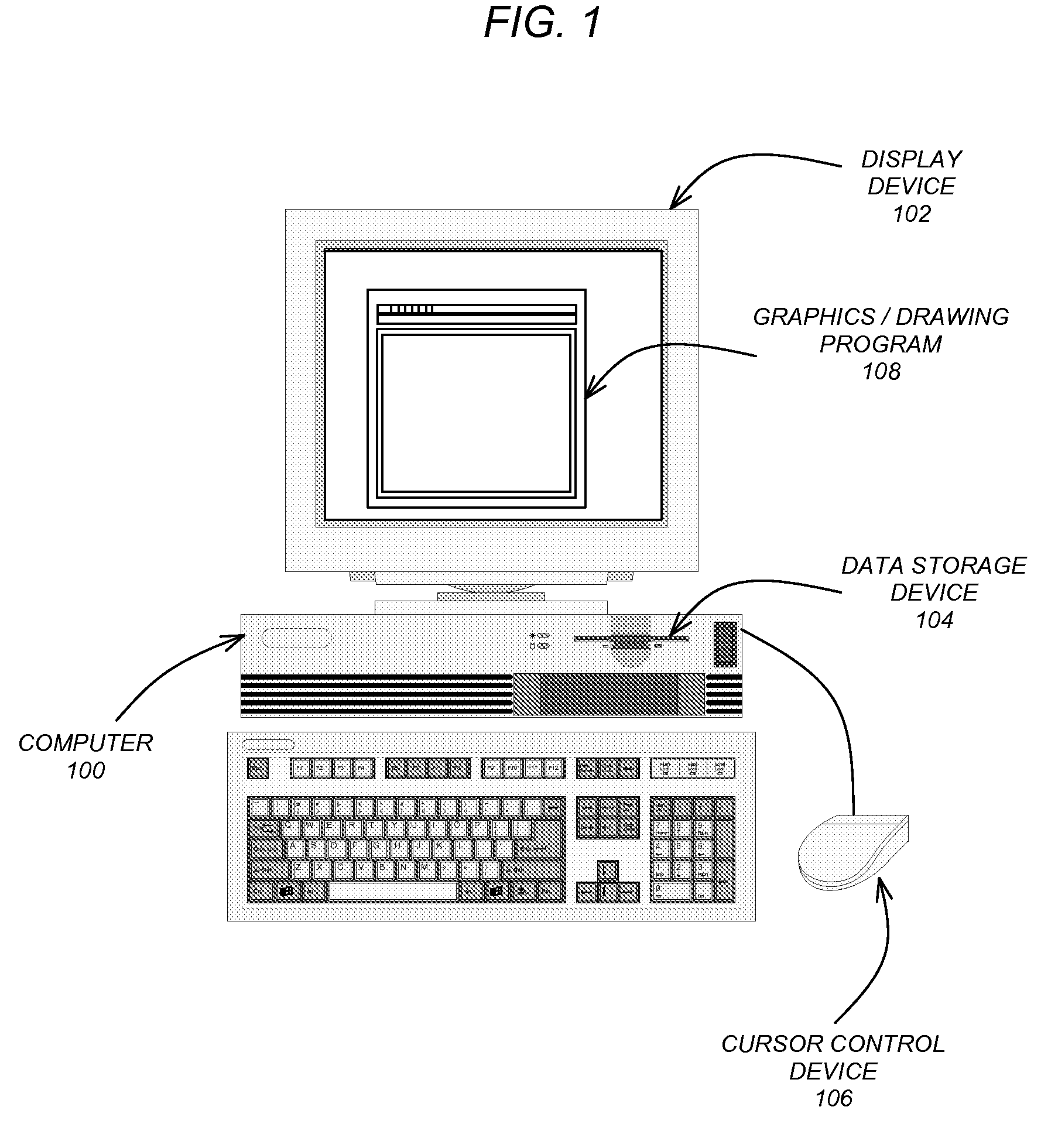
[0021]FIG. 1 is an exemplary hardware and software environment used to implement one or more embodiments of the invention. Embodiments of the invention are typically implemented using a computer 100, which generally includes or are communicatively coupled to, a display device 102, data storage devices 104, cursor control devices 106, and other devices. Those skilled in the art will recognize that any combination of the above components, or any number of different components, peripherals, and other devices, may be used with the computer 100.
[0022]One or more embodiments of the invention are implemented by a co...
PUM
 Abstract
Description
Claims
Application Information