Engine exhaust heat recovery device, and energy supply apparatus using the same

a technology of exhaust gas and heat recovery device, which is applied in the direction of indirect heat exchangers, machines/engines, lighting and heating apparatus, etc., can solve the problems of increasing pressure loss, reducing exhaust heat recovery rate, and losing the kinetic energy of exhaust gas flow rate, so as to reduce exhaust pressure loss, improve exhaust heat recovery rate, and reduce manufacturing cost

Inactive Publication Date: 2010-08-19
YANMAR CO LTD
View PDF7 Cites 17 Cited by
  • Summary
  • Abstract
  • Description
  • Claims
  • Application Information

AI Technical Summary

Benefits of technology

[0017]According to the present invention, it is possible to improve the exhaust heat recovery rate.
[0018]Also, according to the present invention, the catalyst for engine exhaust gas cleaning is housed in the exhaust gas inflow tube, and the space between the inner wall of the heat recovery device and the outer wall of the heat recovery device is caused to be the engine coolant passage, thus enabling the omission of a bent part from the exhaust gas route, which enables reducing exhaust pressure loss as well as lowering manufacturing cost.
[0019]Furthermore, since the catalyst for engine exhaust gas cleanup is housed in the exhaust gas inflow tube, it is possible to cause the overall exhaust gas route to be compact, and lower the cost of the overall exhaust gas route compared to a configuration in which a catalyst housing member is provided separately.

Problems solved by technology

However, the above conventional engine exhaust gas heat recovery device is constituted such that exhaust gas is restricted by a baffle plate, and the heat transmission route is from the exhaust gas to the baffle plate, then to a heat transmission tube or an inner cylinder part (both of which are partition walls of the engine coolant passage), and then to engine coolant.
In other words, the baffle plate is interposed between the exhaust gas and the partition wall of the engine coolant passage, and to that extent, the kinetic energy of the exhaust gas flow rate is lost, and the exhaust heat recovery rate declines.
Also, the exhaust gas passage route becomes complex due to the baffle plate, and therefore in the exhaust gas passage route, the pressure loss increases and dew condensation water readily accumulates.
Particularly, depending on the engine, if nitrogen oxides accumulate in the exhaust gas, there is concern that such nitrogen oxides will condense into nitric acids and corrode the exhaust gas passage route.
Accordingly, exhaust pressure loss increases, and manufacturing cost also rises.
Also, since a catalyst is included in the middle of such a bent part, there is the disadvantage that the structure becomes complex.

Method used


Image

  • Engine exhaust heat recovery device, and energy supply apparatus using the same
  • Engine exhaust heat recovery device, and energy supply apparatus using the same
  • Engine exhaust heat recovery device, and energy supply apparatus using the same

Examples


Embodiment Construction

[0041]The following describes embodiments of the present invention based on the drawings.

[0042]Engine Exhaust Gas Heat Recovery Device not Including a Catalyst

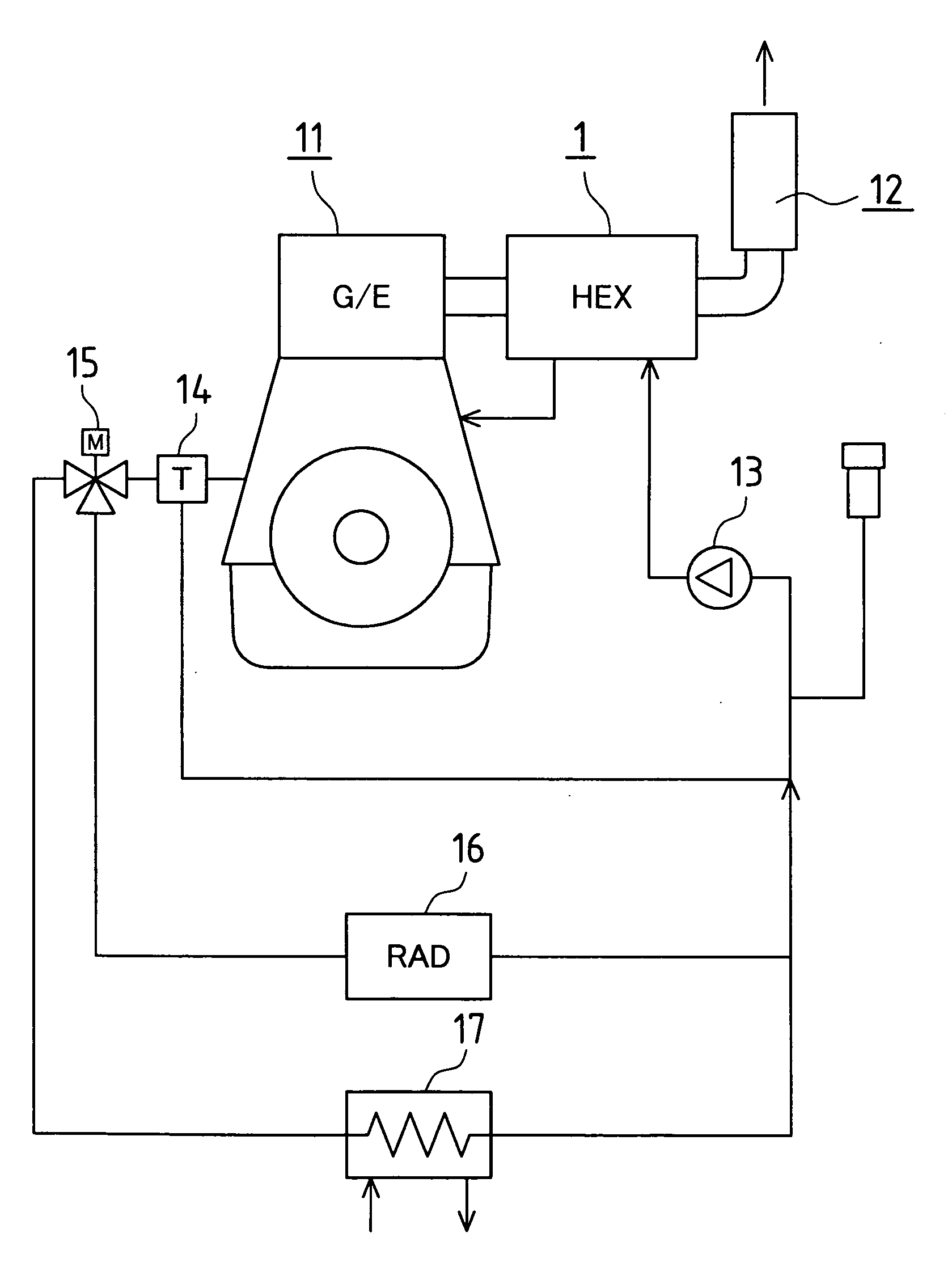
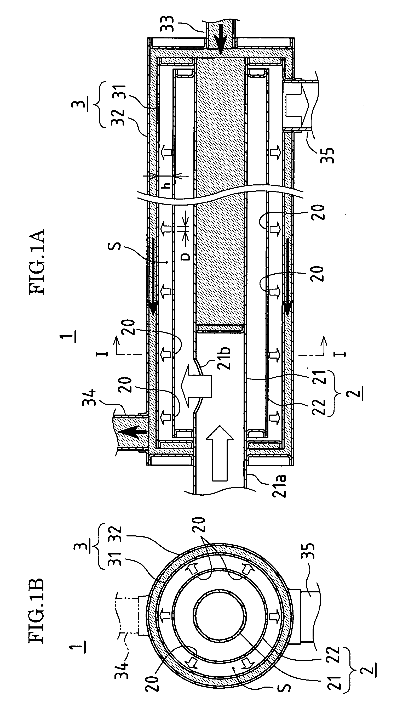
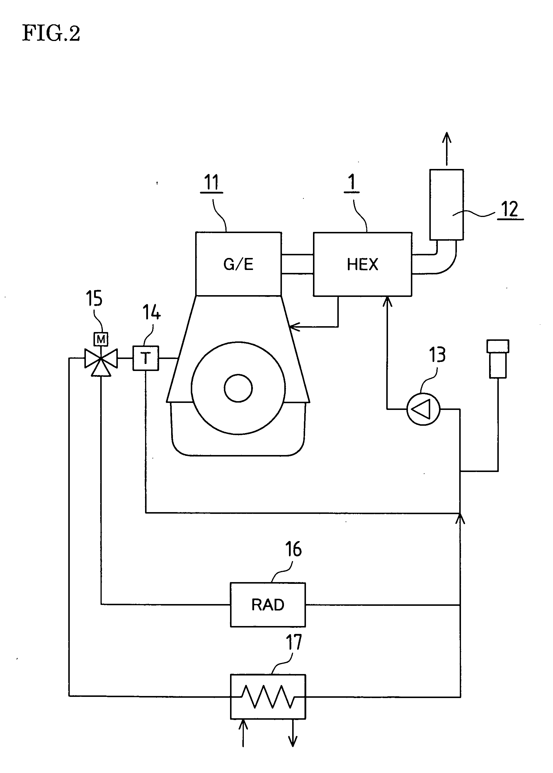
[0043]FIG. 1 shows an engine exhaust gas heat recovery device 1 according to the present invention, and FIG. 2 shows an example of a diagram of a coolant circuit of a gas engine 10 provided with the engine exhaust gas heat recovery device 1.

[0044]Specifically, in this engine exhaust gas heat recovery device 1, a plurality of spray holes 20 facing an inner cylinder tube 31 of a coolant passage 3 are provided in an outer, tube 22 of an exhaust gas inflow tube 2, and exhaust gas is caused to directly collide with the inner cylinder tube 31 of the coolant passage 3.

[0045]As shown in FIG. 2, the engine exhaust gas heat recovery device 1 is provided such that exhaust from an engine 11 that is bound for a silencer 12 passes through the exhaust gas inflow tube 2, and furthermore is provided such that coolant for the engine 11 passes t...


PUM


Abstract

[Problems] Provided is a configuration in which a member is not interposed between exhaust gas and a partition wall of an engine coolant passage, and the exhaust gas is caused to directly collide with the partition wall of the engine coolant passage, thus raising the gas flow velocity in a heat exchange part, which enables further improving the exhaust heat recovery rate.
[Means for Solving Problems] An engine exhaust gas heat recovery device (1) recovers heat from engine exhaust gas by performing heat exchange between the engine exhaust gas and engine coolant. A plurality of spray holes (20) facing an inner cylinder tube (31) of a coolant passage (3) have been provided in an outer tube (22) of an exhaust gas inflow tube (2), and the exhaust gas is caused to directly collide with the inner cylinder tube (31) of the coolant passage (3). A minimum distance from each of the spray holes (20) to the inner cylinder tube (31) of the coolant passage (3) is in a range of 1.5 to 7 times the diameter of the spray holes. A relationship between a total opening area of the spray holes (20) and an exhaust gas flow rate is (total spray hole area/exhaust gas mass flow rate)=2.0 to 4.5 (cm2/(kg/min)).

Description

TECHNICAL FIELD[0001]The present invention relates to an engine exhaust gas heat recovery device used in an engine-driven air conditioning device, a cogeneration system, or the like.BACKGROUND ART[0002]Conventionally, as an engine exhaust gas heat recovery device, there is known a configuration in which heat is recovered from engine exhaust gas by restricting the flow of exhaust gas through the provision of a baffle plate in an exhaust gas passage (see Patent Document 1).[0003]However, the above conventional engine exhaust gas heat recovery device is constituted such that exhaust gas is restricted by a baffle plate, and the heat transmission route is from the exhaust gas to the baffle plate, then to a heat transmission tube or an inner cylinder part (both of which are partition walls of the engine coolant passage), and then to engine coolant. In other words, the baffle plate is interposed between the exhaust gas and the partition wall of the engine coolant passage, and to that exten...

Claims


Application Information

Patent Timeline
Patent Type & Authority Applications(United States)
IPC IPC(8): F01N3/10F01N3/02F01N5/02
CPCF01N1/08Y02B30/52F01N3/2889F01N5/02F01N2240/02F01N2470/02F01N2470/24Y02T10/16F28F13/02F28F13/06F28D7/0066F28D7/103F28D7/106F28D21/0003F01N3/2885Y02T10/12
Inventor FUKUDOME, JIROSUGIMOTO, MASATAKA
Owner YANMAR CO LTD
Why Eureka
Try Eureka