Gas turbine device

a gas turbine and gas turbine technology, applied in the direction of machines/engines, stators, liquid fuel engines, etc., can solve the problems of difficult reduction of low frequency noises generated by gas turbine devices, and achieve the effect of reducing exhaust pressure loss

Inactive Publication Date: 2015-06-18
KAWASAKI HEAVY IND LTD
View PDF7 Cites 9 Cited by
  • Summary
  • Abstract
  • Description
  • Claims
  • Application Information

AI Technical Summary

Benefits of technology

[0013]Generation of the low frequency vibrations or the low frequency noises, which is referred to as the vortex whistle, during the low load operation of the gas turbine engine of the type discussed above results from the reduction in number of the exhaust struts 31 for the purpose of reducing the exhaust pressure loss that is aimed in recent years. For example, while about eight to ten exhaust struts 31 has hitherto been installed, the recent trend is to employ four to six exhaust struts disposed equidistantly in the circumferential direction as shown in FIGS. 4 and 5. Reducing the number of the exhaust struts 31 installed as discussed above may result in that the swirling flow of the exhaust gas moves directly through a large space between the neighboring exhaust struts 31 to thereby form a stream S2 of the exhaust gas then swirling together with intensive vortexes. Accordingly, if a large number of the exhaust struts 31 are used as is the case with the conventional art, the swirling of the exhaust gas can be prevented by the exhaust struts 31 to a certain extent, but the pressure loss of the exhaust gas will then increase.

Problems solved by technology

In contrast thereto, low frequency noises also generated from the gas turbine device are difficult to reduce.

Method used


Image

  • Gas turbine device
  • Gas turbine device
  • Gas turbine device

Examples


Embodiment Construction

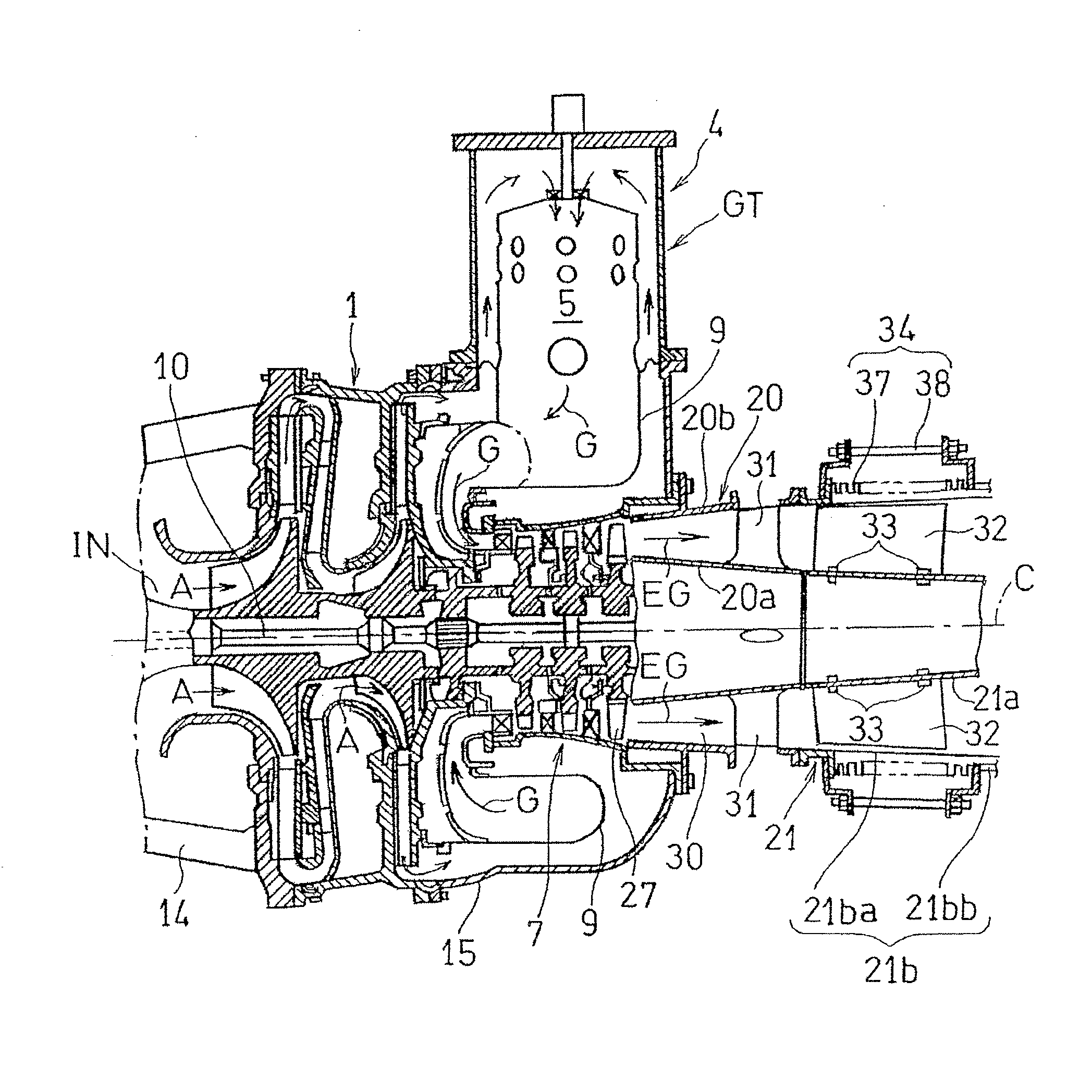
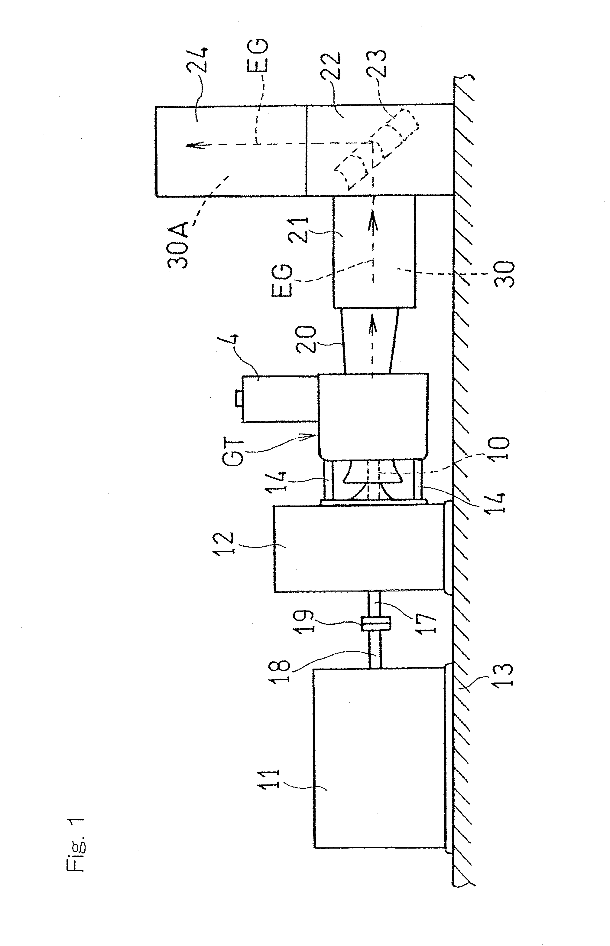
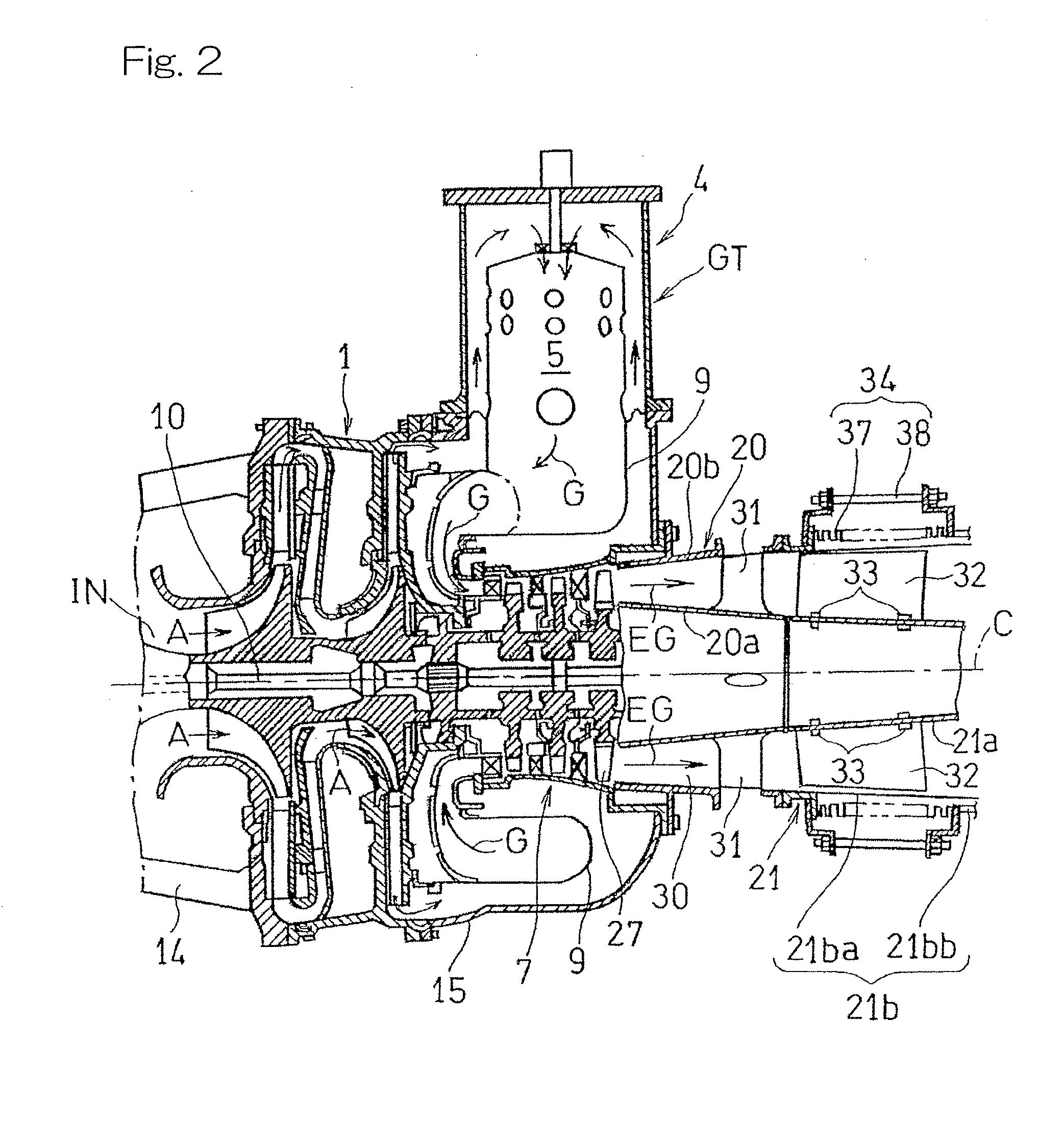
[0031]Hereinafter, an embodiment of the present invention will be described in detail with reference to the accompanying drawings. In particular as shown in FIG. 1, a reduction gear unit 12 having a large weight is fixedly placed on a foundation bed 13, and a gas turbine engine GT is supported by the reduction gear unit 12 in a cantilevered manner through a plurality of, for example, four in the illustrated embodiment, stays 14. The reduction gear unit 12 has a connecting shaft on an input side drivingly connected with a rotary shaft 10 of the gas turbine engine GT and also has a connecting shaft 17 on an output side connected with a drive shaft 18 of an electric generator 11, which forms a load of the gas turbine engine GT, through a coupling 19. An exhaust gas EG discharged substantially horizontally from the gas turbine engine GT is guided into an exhaust chamber 22 through an exhaust diffuser 20 and an exhaust duct 21, subsequently deflected in a substantially vertical direction...


PUM


Abstract

A gas turbine device in which the low frequency vibrations or the low frequency noises during the low load operation can be effectively suppressed with no increase of the pressure loss of the exhaust gas being triggered includes a gas turbine engine provided with an exhaust diffuser forming an upstream portion of an exhaust gas passage, an exhaust strut provided in the diffuser (20), and a swirling flow blocking plate. The swirling flow blocking plate is disposed on a downstream side of the exhaust strut in the exhaust gas passage so as to extend in an axial direction.

Description

[0001]CROSS REFERENCE TO THE RELATED APPLICATION[0002]This application is a continuation application, under 35 U.S.C. §111(a), of international application No. PCT / JP2013 / 072820, filed Aug. 27, 2013, which claims priority to Japanese patent application No. 2012-188346, filed Aug. 29, 2012, the disclosure of which are incorporated by reference in their entirety into this application.BACKGROUND OF THE INVENTION[0003]1. Field of the Invention[0004]The present invention relates to a gas turbine device for driving a power machinery such as, for example, an electric generator by means of a gas turbine engine.[0005]2. Description of Related Art[0006]The gas turbine device is generally apt to generate considerable high frequency noises, but those high frequency noises can be effectively reduced with, for example, the use of a packaging utilizing an enclosure and / or the use of an induction and exhaust silencer. In contrast thereto, low frequency noises also generated from the gas turbine dev...

Claims


Application Information

Patent Timeline
Patent Type & Authority Applications(United States)
IPC IPC(8): F04D29/54
CPCF04D29/541F01D25/30F05D2240/12F05D2260/96F05D2240/15F01D5/143F04D17/122
Inventor YAMASAKI, YOSHIHIROHOSOKAWA, YASUFUMI
Owner KAWASAKI HEAVY IND LTD
Why Eureka
Try Eureka