Flue gas waste heat recovery system for gas thermal equipment

A technology for thermal equipment and flue gas waste heat, applied in lighting and heating equipment, combustion methods, indirect carbon dioxide emission reduction, etc. Effect

Inactive Publication Date: 2016-04-20
CHONGQING SOUTH THERMAL ENG TECH CO
View PDF3 Cites 5 Cited by
  • Summary
  • Abstract
  • Description
  • Claims
  • Application Information

AI Technical Summary

Problems solved by technology

[0006] The embodiment of the present invention solves the technical problem of low energy saving rate in the existing gas thermal equipment heat recovery mode by providing a flue gas waste heat recovery system for gas thermal equipment

Method used


Image

  • Flue gas waste heat recovery system for gas thermal equipment
  • Flue gas waste heat recovery system for gas thermal equipment
  • Flue gas waste heat recovery system for gas thermal equipment

Examples


Embodiment Construction

[0034] In order to make the purpose, technical solutions and advantages of the embodiments of the present invention clearer, the technical solutions in the embodiments of the present invention will be clearly and completely described below in conjunction with the drawings in the embodiments of the present invention. Obviously, the described embodiments It is a part of embodiments of the present invention, but not all embodiments. Based on the embodiments of the present invention, all other embodiments obtained by persons of ordinary skill in the art without creative efforts fall within the protection scope of the present invention.

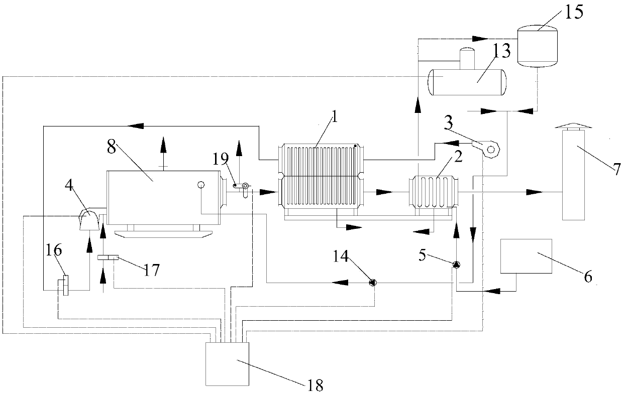
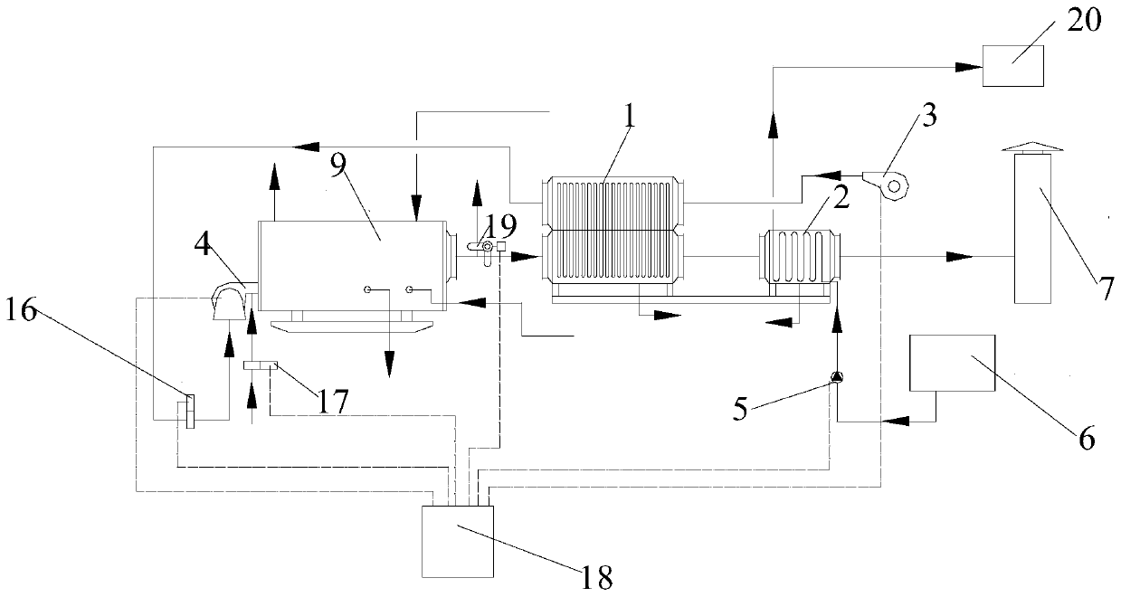
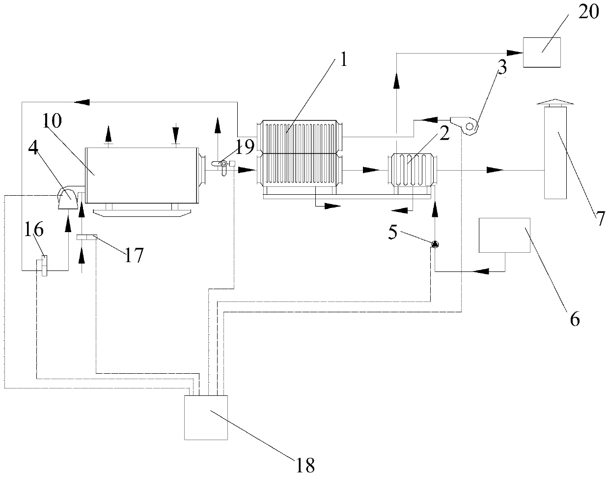
[0035] refer to Figure 1 to Figure 5 As shown, a flue gas waste heat recovery system for gas thermal equipment provided by the embodiment of the present invention includes: gas thermal equipment, heat pipe air heater 1, condensing feed water heater 2, frequency conversion blower 3, combustion equipment 4, frequency conversion pulse type Feed wat...


PUM


Abstract

The invention discloses a flue gas waste heat recovery system for gas thermal equipment. A discharge flue of the gas thermal equipment is communicated to a gas inlet of a heat pipe air heater; an exhaust port of the heat pipe air heater is communicated to a gas inlet of a condensation type feed water heater; an exhaust port of the condensation type feed water heater is communicated to a chimney; an air supply outlet of a variable frequency air feeder is communicated to an air inlet of the heat pipe air heater; an air outlet of the heat pipe air heater is communicated to an inlet of combustion equipment; a water inlet of a variable frequency pulsing water feeding pump is communicated to a water feeding tank; a drainage port of the variable frequency pulsing water feeding pump is communicated to a water inlet of the condensation type feed water heater; a water outlet of the condensation type feed water heater is communicated with heat using equipment; a programmable controller periodically changes a Hedstrom number of the variable frequency pulsing water feeding pump by a program, so that a flow velocity in the condensation type feed water heater is periodically mutated, and thus, the technical problem of low energy-saving rate of an existing gas thermal equipment heat energy recovery mode is solved, and energy saving efficiency of the system is effectively improved.

Description

technical field [0001] The invention relates to the technical field of waste heat recovery of gas thermal equipment, in particular to a waste heat recovery system for flue gas of gas thermal equipment. Background technique [0002] Fossil fuels, as non-renewable resources, are facing depletion in the process of global industrialization, and energy conservation and emission reduction have become a global theme. There are nearly 200,000 sets of gas-fired thermal equipment in operation nationwide, and the annual combustion of gas fuel is about 40-70 billion cubic meters. While consuming a huge amount of resources day after day, the combustion product CO 2 The emissions are about 77 million to 135 million tons per year, and the NOx emissions are correspondingly huge. [0003] The main component of gaseous fuel is CmHn, the CH ratio is relatively small, and the H element occupies a dominant position in the share. During the process of gaseous fuel in the furnace, the H element...

Claims


Application Information

Patent Timeline
Patent Type & Authority Applications(China)
IPC IPC(8): F23J15/08F23L15/00
CPCF23J15/08F23L15/00Y02E20/34
Inventor 李惠军李生根郑绍渝周兴国周德伟
Owner CHONGQING SOUTH THERMAL ENG TECH CO
Why Eureka
Try Eureka