Sensor element

Active Publication Date: 2010-08-19
ROBERT BOSCH GMBH
View PDF10 Cites 5 Cited by
  • Summary
  • Abstract
  • Description
  • Claims
  • Application Information

AI Technical Summary

Benefits of technology

[0006]Proceeding from this existing art, a sensor element for sensing accelerations in three spatial directions, which furn

Problems solved by technology

The resulting configuratio

Method used


Image

  • Sensor element
  • Sensor element
  • Sensor element

Examples


Embodiment Construction

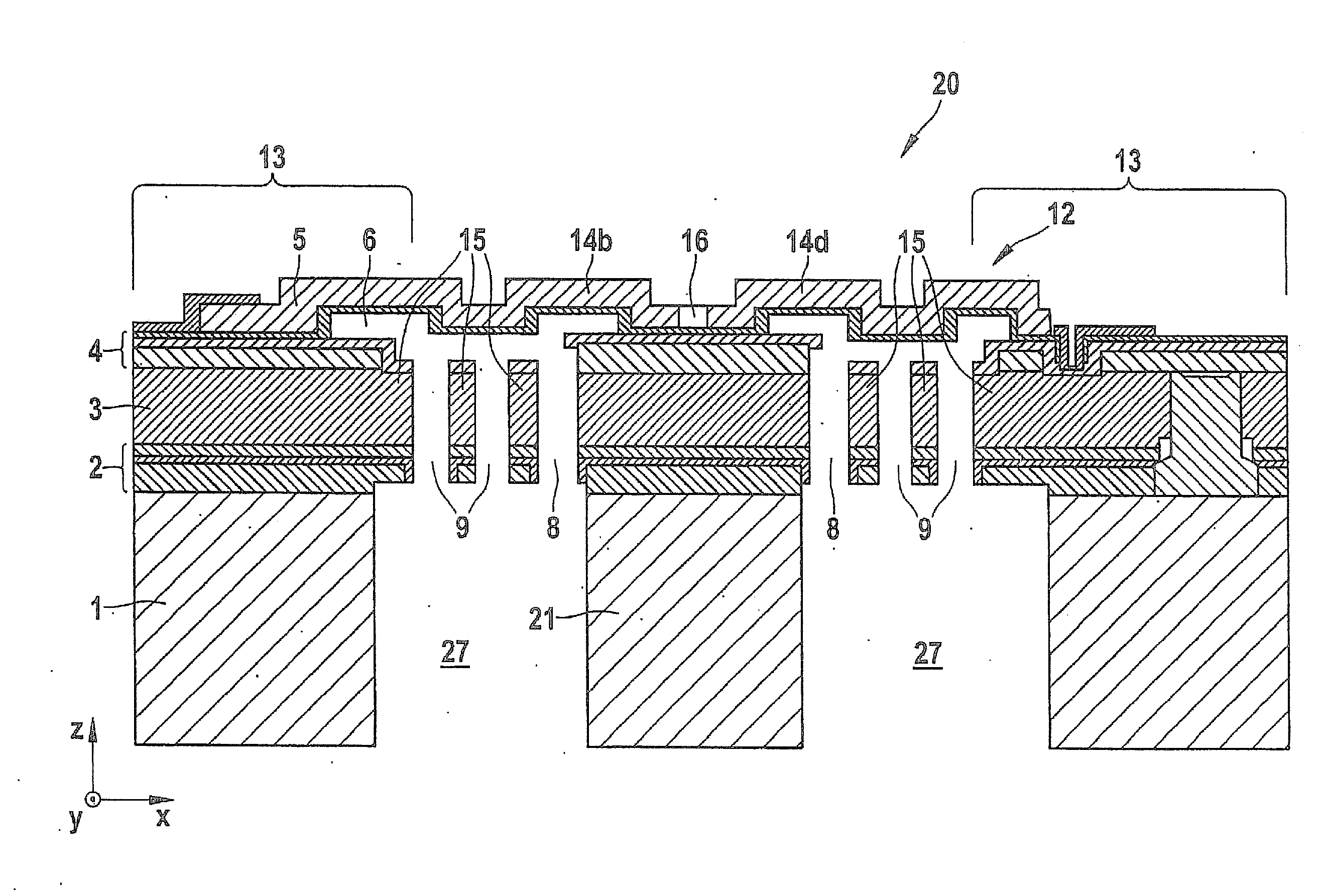
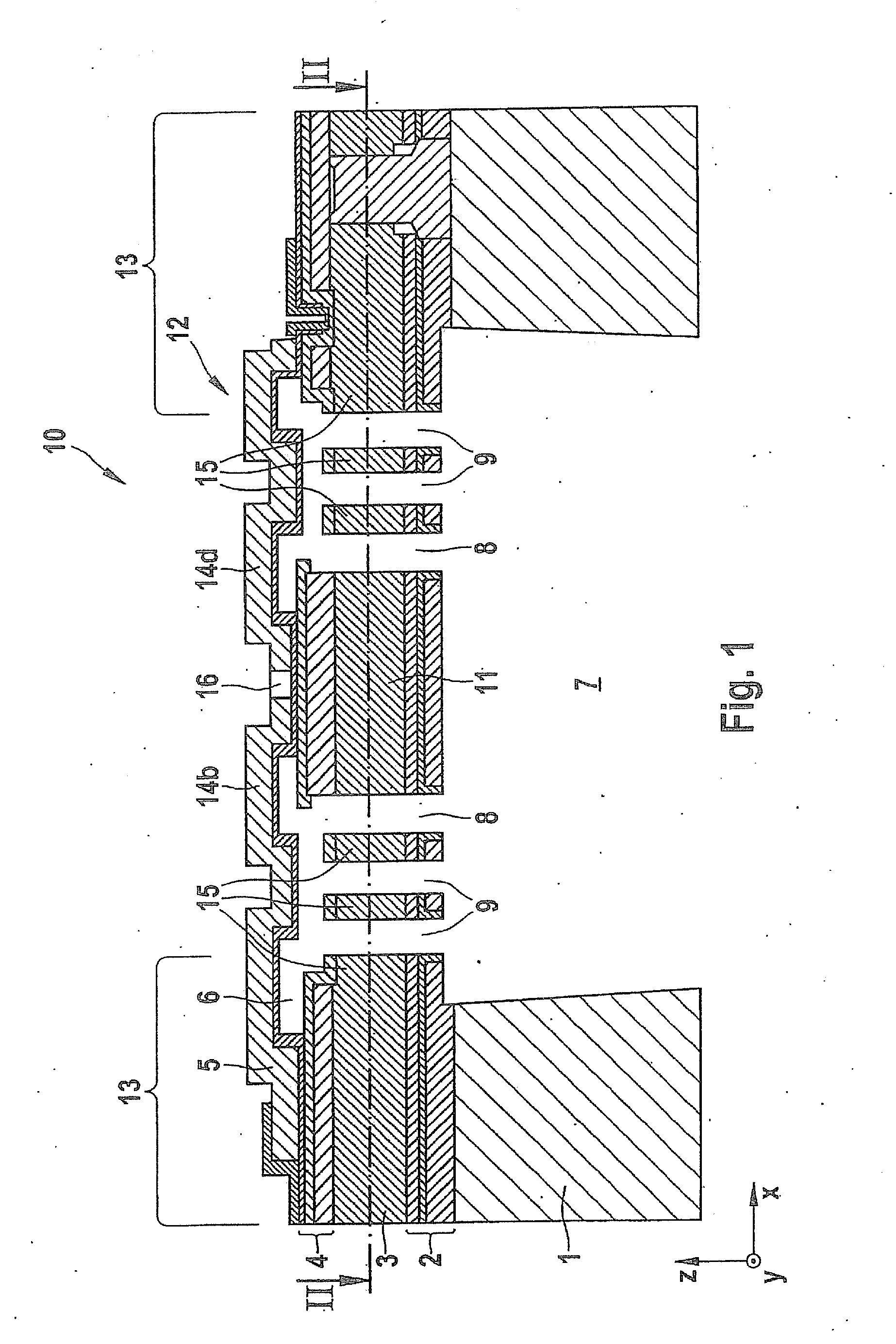
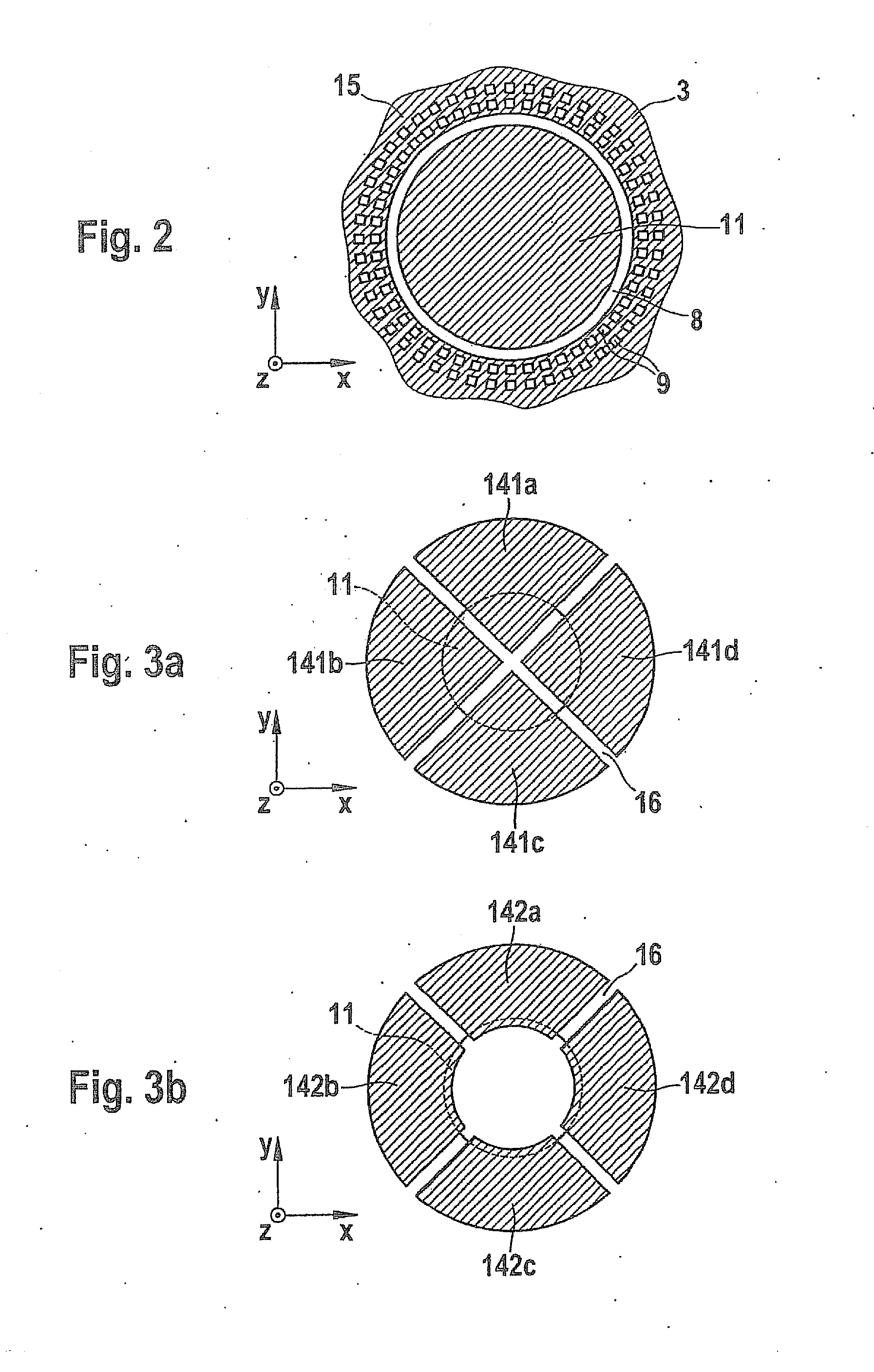
[0020]Sensor element 10 depicted in FIG. 1, for sensing accelerations in three spatial directions, encompasses a seismic mass 11 that is suspended in a frame 13 via a diaphragm structure 12 so that it is deflectable in all three spatial directions. The deflections of seismic mass 11 are sensed capacitively. Diaphragm structure 12 of sensor element 10 encompasses for this purpose, according to the exemplary embodiments and / or exemplary methods of the present invention, four electrode regions 14a to 14d that are electrically separated from one another, of which only electrode regions 14b and 14d are evident in the sectioned depiction of FIG. 1. All four electrode regions 14a to 14d are mechanically coupled via seismic mass 11; this is illustrated in particular by FIGS. 3a to 3d. Sensor element 10 further encompasses a stationary counterelectrode 15 for electrode regions 14a to 14d, is embodied below the deformable region of diaphragm structure 12.

[0021]In the exemplifying embodiment d...


PUM


Abstract

A sensor element is provided for sensing accelerations in three spatial directions, which furnishes reliable measurement results and moreover can be implemented economically and with a small configuration. The sensor element encompasses at least one seismic mass deflectable in three spatial directions, a diaphragm structure that functions as a suspension mount for the seismic mass, and at least one stationary counterelectrode for capacitive sensing of the deflections of the diaphragm structure. According to the exemplary embodiments and/or exemplary methods of the present invention, the diaphragm structure encompasses at least four electrode regions, electrically separated from one another, that are mechanically coupled via the seismic mass.

Description

FIELD OF THE INVENTION[0001]The present invention relates to a sensor element for sensing accelerations in three spatial directions, having at least one seismic mass deflectable in three spatial directions, having a diaphragm structure that functions as a suspension mount for the seismic mass and encompasses at least one electrode, and having at least one stationary counterelectrode for capacitive sensing of the deflections of the diaphragm structure.BACKGROUND INFORMATION[0002]In the consumer sector in particular, there is an increasing demand for economical acceleration sensors for all three spatial directions having a small configuration and the lowest possible energy consumption.[0003]Gang Li et al., “Design and fabrication of a highly symmetrical capacitive triaxial accelerometer,” Journal of Micromechanics and Microengineering 11 (2001) 48-54, describe a micromechanical sensor element of the kind cited initially with which accelerations in all three spatial directions can be s...

Claims


Application Information

Patent Timeline
IPC IPC(8): G01P15/125
CPCG01P15/0802G01P15/18G01P15/125G01P2015/084
Inventor ZOELLIN, JOCHENFRANKE, AXELTEEFFELEN, KATHRINLEINENBACH, CHRISTINA
Owner ROBERT BOSCH GMBH
Why Eureka
Try Eureka