Internal cooling system for a radome

a cooling system and radome technology, applied in the field of radomes, to achieve the effect of increasing the heat that may be removed from the radome, dissipating heat, and increasing the amount of heat dissipation

Active Publication Date: 2010-08-19
RAYTHEON CO
View PDF15 Cites 14 Cited by
  • Summary
  • Abstract
  • Description
  • Claims
  • Application Information

AI Technical Summary

Benefits of technology

[0005]Certain embodiments of the disclosure may provide certain technical advantages. In some embodiments, the amount of heat that may be removed from a radome may be increased. For example, known combinations of passive and modified-passive heat removal systems may remove heat up to approximately 30 Watts / inch2 under certain conditions. Including the internal cooling system of the present disclosure with the passive and modified-passive heat removal systems of certain embodiments may increase heat removal to at least approximately 50 Watts / inch2 under similar conditions. In addition to increasing the amount heat dissipated, the internal cooling system may dissipate heat from the relatively hot layers of the radome nearest the heat source, the antenna.

Problems solved by technology

In addition to increasing the amount heat dissipated, the internal cooling system may dissipate heat from the relatively hot layers of the radome nearest the heat source, the antenna.

Method used


Image

  • Internal cooling system for a radome
  • Internal cooling system for a radome
  • Internal cooling system for a radome

Examples


Embodiment Construction

[0013]It should be understood at the outset that, although example implementations of embodiments are illustrated below, the present invention may be implemented using any number of techniques, whether currently known or not. The present invention should in no way be limited to the example implementations, drawings, and techniques illustrated below. Additionally, the drawings are not necessarily drawn to scale.

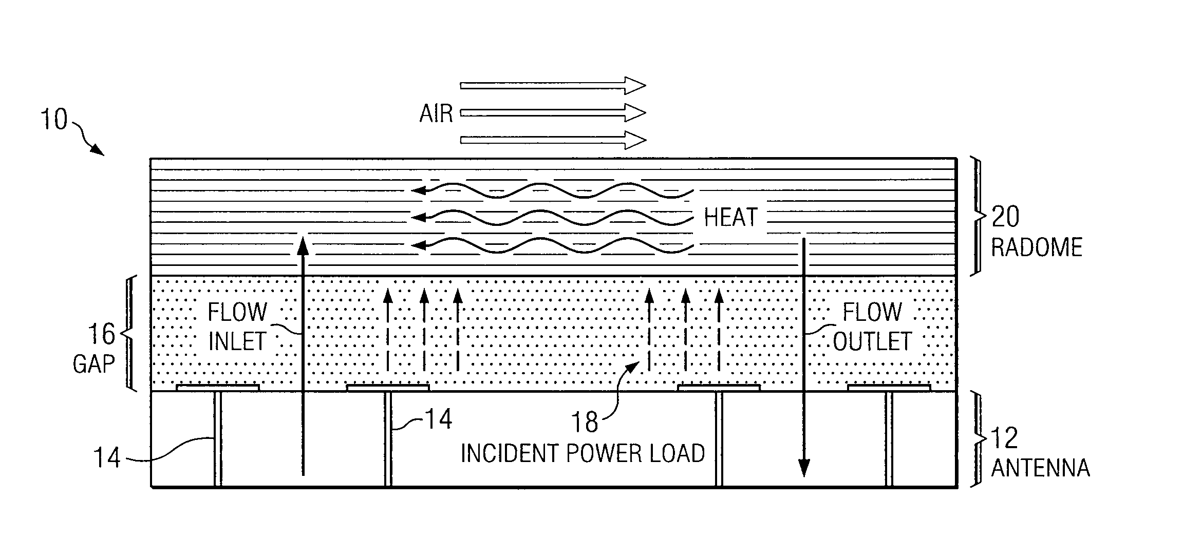
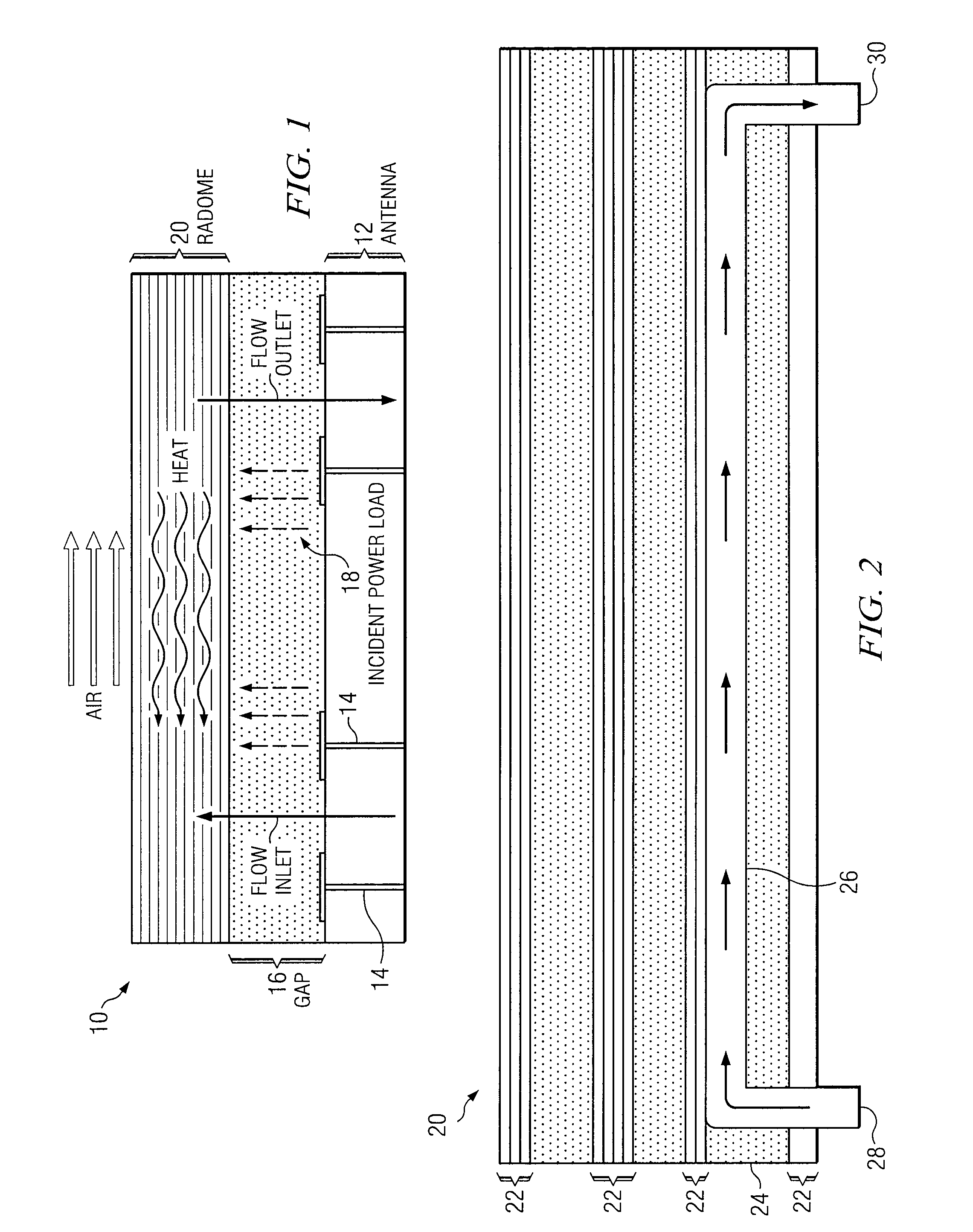
[0014]As previously described, a radome may be used to protect an antenna from the environment. The power transmitted by the antenna, however, may have the effect of heating the radome. Exposure to heat may compromise the electrical performance of the radome, may increase the infrared signature of the radome, and / or may cause the layers of the radome to separate, blister, or delaminate. Exposure to substantial amounts of heat may be a particular problem for radomes that are configured with large, high-powered antennas, such as certain active electronically scanned array (AESA)...


PUM


Abstract

According to one embodiment, a radome includes two dielectric layers separated by an internal layer. The internal layer is configured with an internal cooling system including a fluid channel that receives a fluid through an inlet port, conducts heat from the radome to the fluid, and exhausts the heated fluid through an outlet port.

Description

RELATED APPLICATIONS[0001]This application claims priority to U.S. Provisional Patent Application Ser. No. 61 / 137,524, entitled “HEAT REMOVAL SYSTEM FOR A RADOME,” which was filed on Jul. 30, 2008. U.S. Provisional Patent Application Ser. No. 61 / 137,524 is hereby incorporated by reference.TECHNICAL FIELD OF THE DISCLOSURE[0002]This disclosure relates generally to radomes, and more particularly to an internal cooling system for a radome.BACKGROUND OF THE DISCLOSURE[0003]Antennas, such as those that operate at microwave frequencies, typically include multiple radiating elements having relatively precise structural characteristics. To protect these elements, a covering referred to as a radome may be configured between the elements and the ambient environment. The radome may shield the radiating elements of the antenna from various environmental aspects, such as precipitation, humidity, solar radiation, or other forms of debris that may compromise the performance of the antenna. The rad...

Claims


Application Information

Patent Timeline
Patent Type & Authority Applications(United States)
IPC IPC(8): F28D15/00H01Q1/42
CPCH01Q1/002H01Q1/422H01Q1/02
Inventor CHEN, KEVIN W.ALLEN, BRANDON H.RUMMEL, KERRIN A.SEIFERMAN, GARY L.WEBER, RICHARD M.HAROKOPUS, WILLIAM P.
Owner RAYTHEON CO
Why Eureka
Try Eureka