Chamfered Pointed Enhanced Diamond Insert

Active Publication Date: 2010-08-19
SCHLUMBERGER TECH CORP
View PDF43 Cites 11 Cited by
  • Summary
  • Abstract
  • Description
  • Claims
  • Application Information

AI Technical Summary

Benefits of technology

[0009]A substantially circumferential edge may be formed at an interface between the substantially conical portion and the apex's radius. The substantially circumferential edge may be radiused or chamfered to reduce the sharpness of the e

Problems solved by technology

These tools are commonly subjected to high impact loads, vibrations, high temperatures and pressures, and other adverse conditions.
Frequent replacement of the high-impact resistant tools is undesirable, though often necessary due to spalling, delamination, and abrasive wear.

Method used


Image

  • Chamfered Pointed Enhanced Diamond Insert
  • Chamfered Pointed Enhanced Diamond Insert
  • Chamfered Pointed Enhanced Diamond Insert

Examples


Embodiment Construction

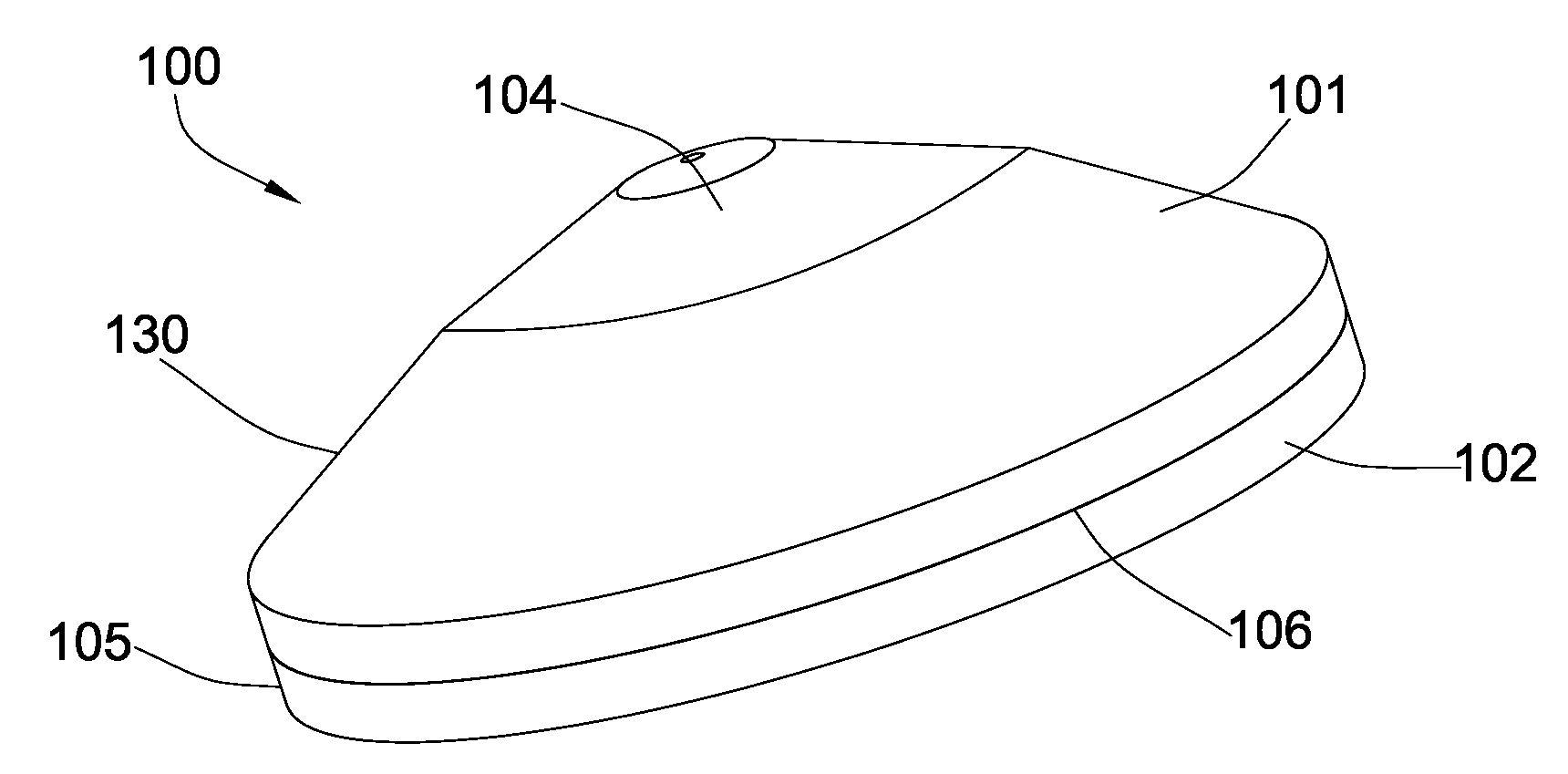
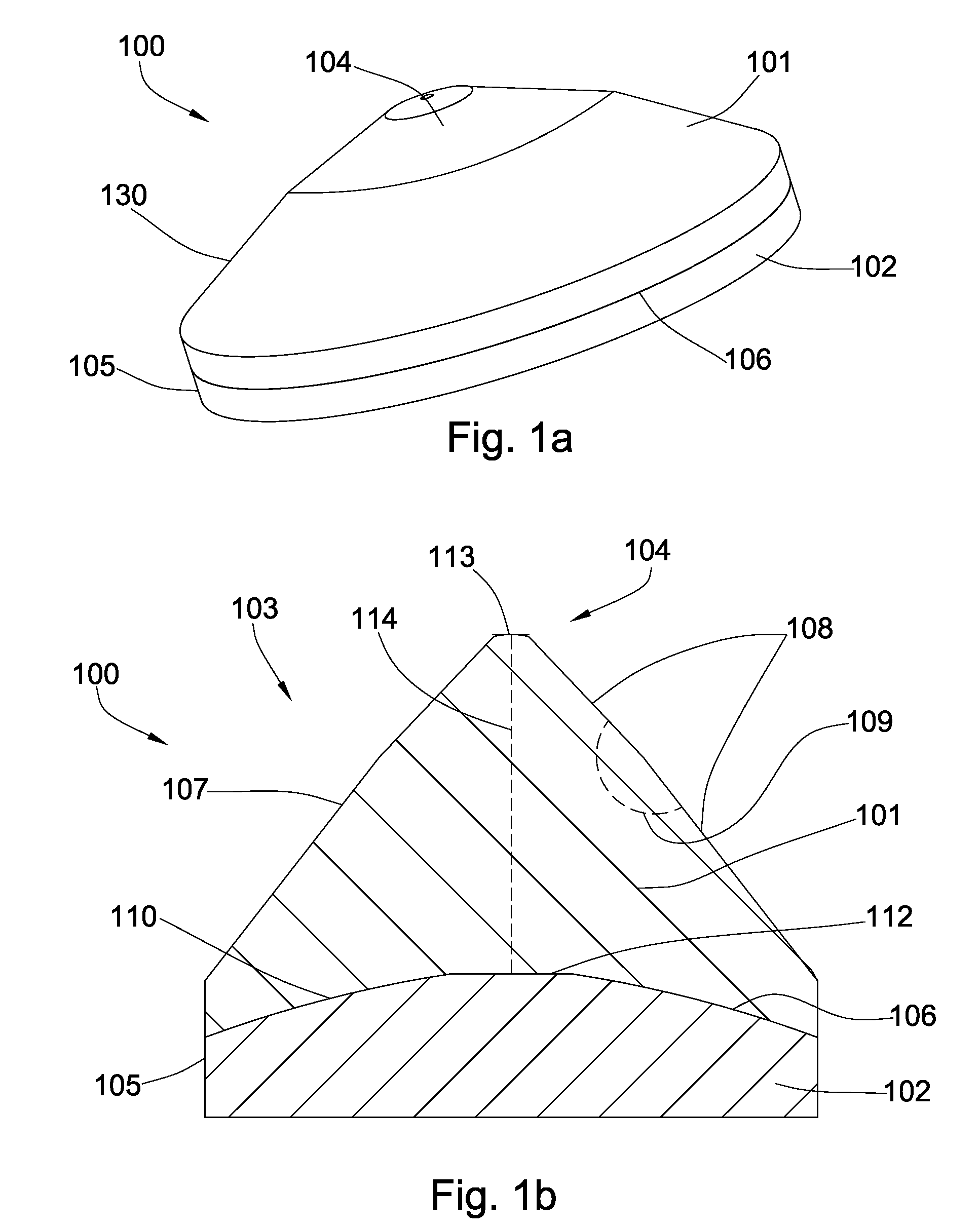
[0026]Referring now to the figures, FIG. 1a discloses a high impact tool 100 according to the present invention. The high impact tool 100 comprises superhard material 101 bonded to a carbide substrate 102 at a non-planer interface 106. The superhard material 101 comprises a substantially conical portion 103 with an apex 104. The superhard material 101 may comprise polycrystalline diamond, cubic boron nitride, or another suitably hard crystalline material. The carbide substrate 102 may comprise a generally cylindrical rim 105, and may be adapted for attachment to an implement such as a drag bit by brazing or an interference fit. In some embodiment, the tool 100 will be used in picks, milling picks, trenching picks, mining picks, bits, roller cone bits, and percussion bits.

[0027]FIG. 1b discloses a high impact tool 100 according to the present invention, comprising a superhard material 101 with substantially conical geometry 103 bonded to a carbide substrate 102 at a non-planer interf...


PUM


Abstract

In one aspect of the present invention, a high-impact resistant tool comprises a superhard material bonded to a substrate at a non-planer interface, the superhard material comprising substantially pointed geometry with a substantially conical portion, the substantially conical portion comprising a tapered side wall with at least two different, contiguous slopes that form an angle greater than 135 degrees, and the thickness from an apex of the superhard material to the interface is greater than the thickness of the substrate.

Description

BACKGROUND OF THE INVENTION[0001]The invention relates to high-impact resistant tools, specifically those used in machinery such as earth-boring drill bits. These tools are commonly subjected to high impact loads, vibrations, high temperatures and pressures, and other adverse conditions. Frequent replacement of the high-impact resistant tools is undesirable, though often necessary due to spalling, delamination, and abrasive wear. Accordingly, efforts have been made to increase the life of such tools.[0002]Such efforts are disclosed in U.S. Pat. No. 4,109,737 to Bovenkerk, which is herein incorporated by reference for all that it contains. Bovenkerk discloses a rotary drill bit for rock drilling comprising a plurality of cutting elements mounted by interference-fit in recesses in the crown of the drill bit. Each cutting element comprises an elongated pin with a thin layer of polycrystalline diamond bonded to the free end of the pin.[0003]U.S. Pat. No. 5,544,713 to Dennis, which is he...

Claims


Application Information

Patent Timeline
IPC IPC(8): E21B10/56E21B10/46B05D3/12
CPCE21B10/55
Inventor HALL, DAVID R.CROCKETT, RONALD B.
Owner SCHLUMBERGER TECH CORP
Why Eureka
Try Eureka