Load management controller

a load management and controller technology, applied in the integration of power network operation systems, sustainable buildings, greenhouse gas reduction, etc., can solve the problems of high electricity supply costs to consumers, more harmful to the environment, and particular dilemmas of consumers, so as to manage their electricity generation and transmission plants more effectively and efficiently

Inactive Publication Date: 2010-08-19
COOPER TIMOTHY PATRICK +2
View PDF5 Cites 84 Cited by
  • Summary
  • Abstract
  • Description
  • Claims
  • Application Information

AI Technical Summary

Benefits of technology

[0030]By having such a load management controller, the load on the grid may be more effectively managed as the loads may be reduced in the household and furthermore any additional electricity not needed by the household may be supplied back onto the g

Problems solved by technology

There are numerous problems with this system and method of supplying electricity.
First of all, typically, the consumer has a limited choice of electricity provider and in many cases the consumer will have only one electricity provider willing to provide them with their electricity needs.
This leads to monopolies or effective monopolies for the electricity providers resulting in high electricity supply costs to the consumer.
Secondly, many of the electricity generating stations operate using relatively environmentally unfriendly electricity generation methods and the more electricity used by the consumer, the more harmful to the environment they will be.
This is a particular dilemma to those consumers that are environmentally aware.
Although this is often seen as a more cost effective and environmentally friendly solution in the long term, there are also problems with using micro-generators as a sole electricity supply source.
The greatest problem being that the micro-generators that operate using renewable energy supplies, such as PV arrays, are not guaranteed to supply sufficient amounts of energy to a household at all times and therefore the micro-generators are typically used in conjunction with rather than replacing the grid electricity supply.
This is often undesirable because electricity that flows back to the grid is subject to distribution and transmission losses.
It is also une

Method used


Image

  • Load management controller
  • Load management controller
  • Load management controller

Examples


Embodiment Construction

[0049]The invention will now be more clearly understood from the following description of some embodiments thereof, given by way of example only, in which:—

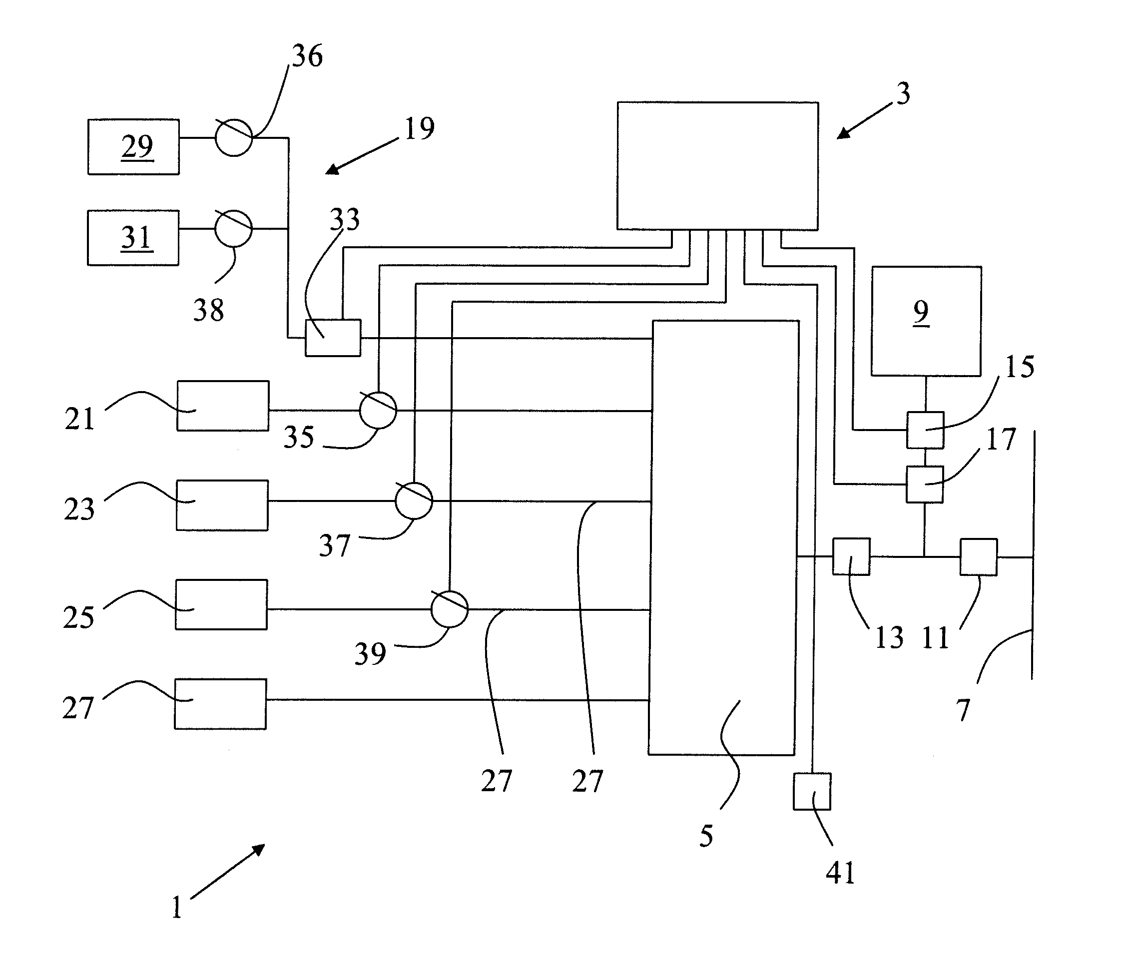
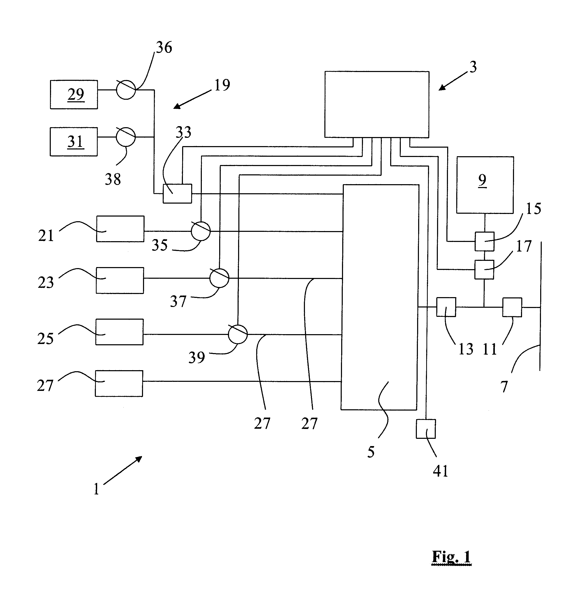
[0050]FIG. 1 is a diagrammatic representation of a household electrical installation incorporating the load management controller according to the present invention;

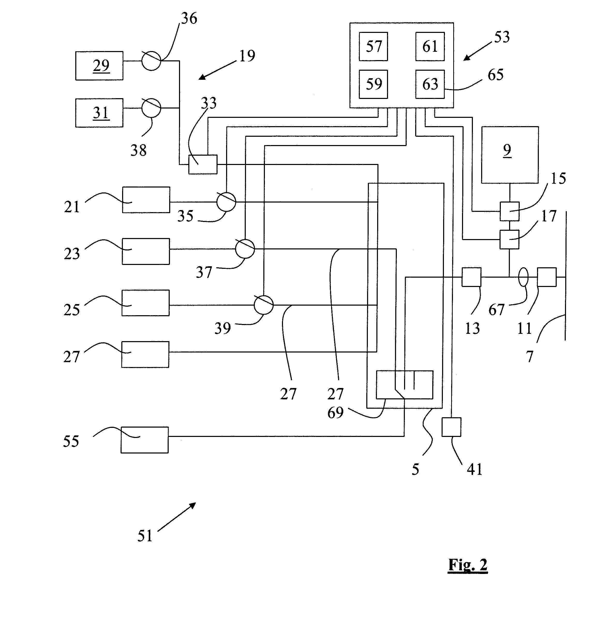
[0051]FIG. 2 is a diagrammatic representation of a load management controller in an alternative household electrical installation;

[0052]FIG. 3 is a diagrammatic representation of a load management controller in a further alternative household electrical installation; and

[0053]FIG. 4 is a diagrammatic representation of the components of the load management controller.

[0054]Referring to FIG. 1, there is shown a household electrical installation, indicated generally by the reference numeral 1, incorporating a load management controller 3. The household electrical installation 1 comprises a main panel 5 fed by a pair of electrical supplies, one of which is the grid supply...


PUM


Abstract

The present invention relates to a load management controller for a household electrical installation comprising a pair of electricity supplies, a grid supply and a micro-generator supply, providing electricity to a plurality if sub-circuits. The household electrical installation has means to monitor the amount of electricity being supplied by the micro-generator supply and the amount of electricity being consumed in the household. The load management controller has means to access and use that information to control the supply of electricity to an energy storage sub-circuit to route surplus electricity supplied by the micro-generator to the energy storage sub-circuit. Furthermore, the load management controller can communicate with a remote electricity supplier to control the loads in the household to achieve better grid management and efficiency.

Description

INTRODUCTION[0001]This specification relates to a load management controller for a household electrical installation.[0002]Heretofore, the vast majority of households have been provided with their electricity supply from a third party electricity provider. General speaking, the electricity provider generates the electricity in large electricity generating stations and thereafter supplies that electricity over an electricity supply grid to their customers. There are numerous problems with this system and method of supplying electricity. First of all, typically, the consumer has a limited choice of electricity provider and in many cases the consumer will have only one electricity provider willing to provide them with their electricity needs. This leads to monopolies or effective monopolies for the electricity providers resulting in high electricity supply costs to the consumer. Secondly, many of the electricity generating stations operate using relatively environmentally unfriendly el...

Claims


Application Information

Patent Timeline
IPC IPC(8): H02J3/06
CPCH02J3/14H02J3/382H02J2003/143Y02B70/3225Y02B70/3266Y02E70/30Y04S20/222Y04S20/242H02J3/383H02J3/386Y02E10/563Y02E10/566Y02E10/763Y02B10/14H02J3/32H02J2310/14H02J2300/28H02J2300/20H02J2300/24H02J3/381Y02B10/10Y02B70/30Y02E10/56Y02E10/76
Inventor COOPER, TIMOTHY PATRICKHARRIS, COLIN DAVIDBEAN, THOMAS LAURENCE
Owner COOPER TIMOTHY PATRICK
Why Eureka
Try Eureka