Standby operation of a resonant power converter

a technology of resonant power converter and standby mode, which is applied in the direction of electric variable regulation, process and machine control, instruments, etc., can solve the problems of low efficiency of resonant llc technology, inability to avoid hard switching, and low efficiency of low load operation, so as to reduce spurious or unanticipated errors, and control effective and accurate

Active Publication Date: 2010-08-19
NXP BV
View PDF7 Cites 22 Cited by
  • Summary
  • Abstract
  • Description
  • Claims
  • Application Information

AI Technical Summary

Benefits of technology

[0019]According to a yet further aspect of the invention, there is provided a method of operating a resonant power converter further including the step of regulating the output power, by controlling the duration of the first sub period, or preferably by controlling the moment at which the second switch is opened at the start of the second dead time in combination with the duration of the first sub-period. This has the advantage of effective and accurate control.
[0020]Preferably a parameter related to the voltage at the node between the first switch and the second switch less the voltage (Vcr) across the capacitor (Cr) is used to control the moment at which the second switch is opened at the start of the second dead time by opening the switch when the parameter is at a first threshold level, and control of the duration of the first sub-period is effected by opening the first switch when the parameter is at a second threshold level. Advantageously, this control method provides robust control and reduces spurious or unanticipated errors arising due to changes to external or other conditions such as supply voltage or output load voltage.

Problems solved by technology

However, one of the main disadvantages for resonant LLC technology is its relatively low efficiency under low load operation (when operated in the most common operation mode, that is, using a fifty percent duty cycle).
Losses in this mode of operation may be a multiple of the required stand-by power.
Whilst switched on, hard switching cannot be avoided.
However, at very low power levels, the benefits achieved by this method are reduced as follows: firstly, at increasingly low power levels, increasingly more resonant cycles are skipped before the LSS is turned off to restart the switching cycle.
As the resonating current resonates in the primary side resonant circuit however there will be some leakage resulting in a damping of the resonance.
This will lead to larger core losses, since these losses are proportional to the amplitude of the magnetising current raised to the power 2.3.
A second disadvantage of operating the power converter in this mode is that of its sensitivity to input voltage variations, since during the HSS conduction period the ratio between the current directly transferred to load and current built up in the magnetising inductors decreases as the voltage decreases.
This could lead to a situation where no power at all is converted to the load should the input voltage fall to below approximately seventy five percent of its nominal value.
Additional circuitry is required to overcome this, with the consequence of further efficiency decreases and increased costs associated with the additional circuitry.

Method used


Image

  • Standby operation of a resonant power converter
  • Standby operation of a resonant power converter
  • Standby operation of a resonant power converter

Examples


Embodiment Construction

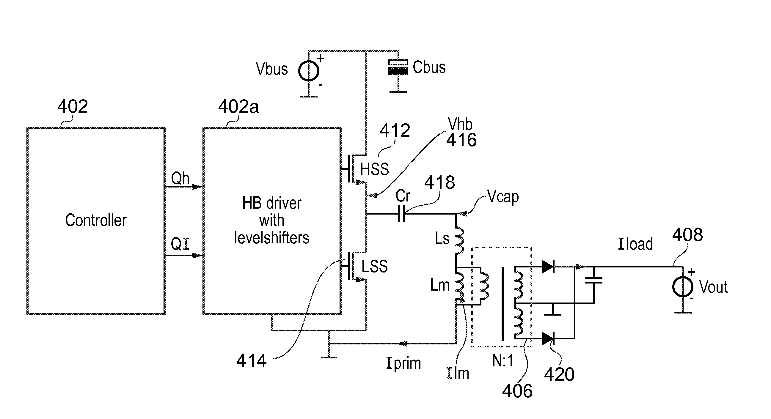
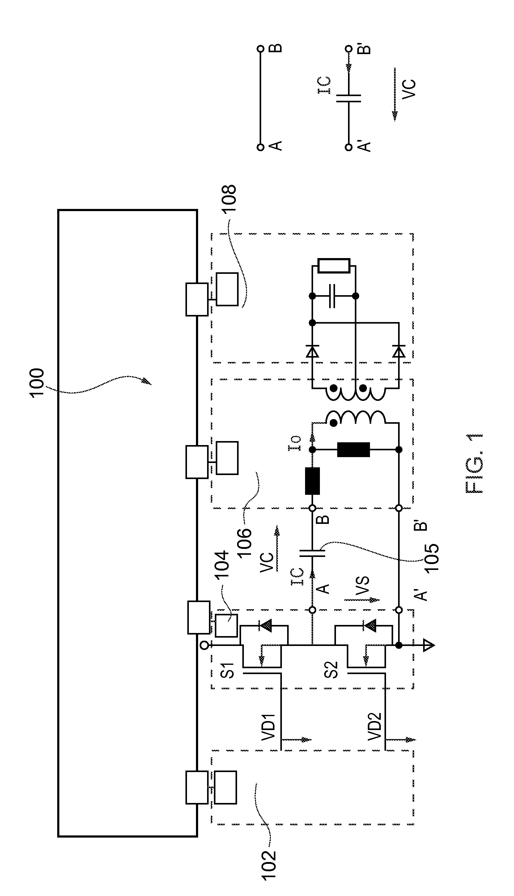
[0039]FIG. 1 shows a resonant power supply 100 with a non-grounded (left) and a grounded (right) resonant capacitor. Resonant power supply 100 comprises a driver / controller 102, a half-bridge 104, a transformer 106 and an output / load 108. An inverter is formed by the half-bridge 104: The inverter includes two switches, S1 and S2. S1 is the high side switch (HSS) or control FET, and S2 is the low-side switch (LSS) or sync FET. A person skilled in the art will understand that the converter could equally well contain a full-bridge with two high side switches and two low side switches. The source of S1 is connected to the drain of S2, at a half-bridge node or switch node point A, which is connected to transformer 106 at B via a capacitor 105. Alternatively, the capacitor may connect the low side of the LSS (at A′) to the transformer at B′.

[0040]In overview, during normal operation the switches S1 and S2 are alternately switched on. The voltage at the half-bridge node point A is thus alt...


PUM


Abstract

A method of operating a resonant power supply in standby mode is disclosed, in which the switching period of the power supply is longer than the resonance period. The power converter is operated in normal mode for a significant fraction of one resonance period. Efficient operation is maintained, despite the switching period being extended beyond the resonance period, by using resonance current to enable soft switching, where this is beneficial, and dumping the resonance current into the load where this is more beneficial. Control methodologies to regulate the output power are also disclosed.

Description

FIELD OF THE INVENTION[0001]The present invention relates to a power supplies and in particular the invention relates to a standby mode of operation of a resonant type DC-DC power converter.[0002]The present invention is particularly relevant to devices that require a normal level of power as well as a lower level of power for use in a standby mode. Examples of such devices are consumer electronic devices such as computers, television and the like.BACKGROUND OF THE INVENTION[0003]Power converters for consumer applications operate at partial load under standby conditions for a relatively large part of their lifetime. Whilst functioning in this operation mode, it is desirable to draw power from the mains supply at as low a level as is conveniently possible. Therefore it is desirable to use a power converter design for the power supply which operates with a high efficiency not only under full load conditions, but also for partial load, especially at low standby mode.[0004]Power supplie...

Claims


Application Information

Patent Timeline
Patent Type & Authority Applications(United States)
IPC IPC(8): H02M3/337
CPCH02M3/3376H02M2001/0032Y02B70/1491Y02B70/16H02M2001/0058Y02B70/1433H02M1/0032H02M1/0058Y02B70/10
Inventor HALBERSTADT, HANS
Owner NXP BV
Why Eureka
Try Eureka