Wheel bearing device and manufacturing method therefor
- Summary
- Abstract
- Description
- Claims
- Application Information
AI Technical Summary
Benefits of technology
Problems solved by technology
Method used
Image
Examples
first embodiment
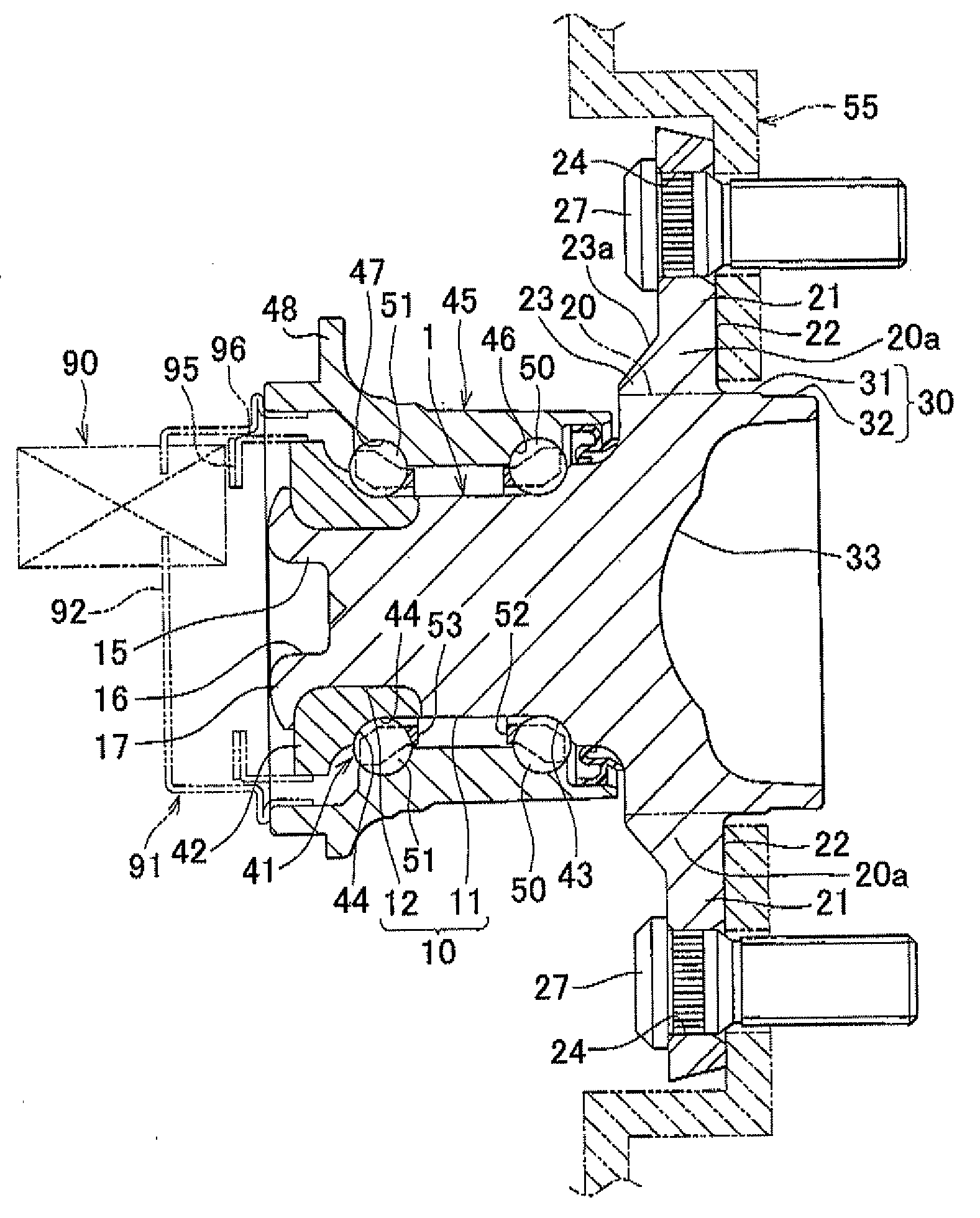
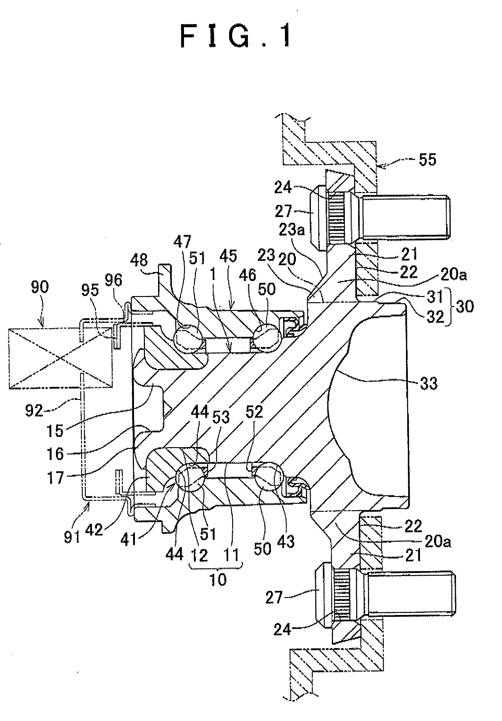
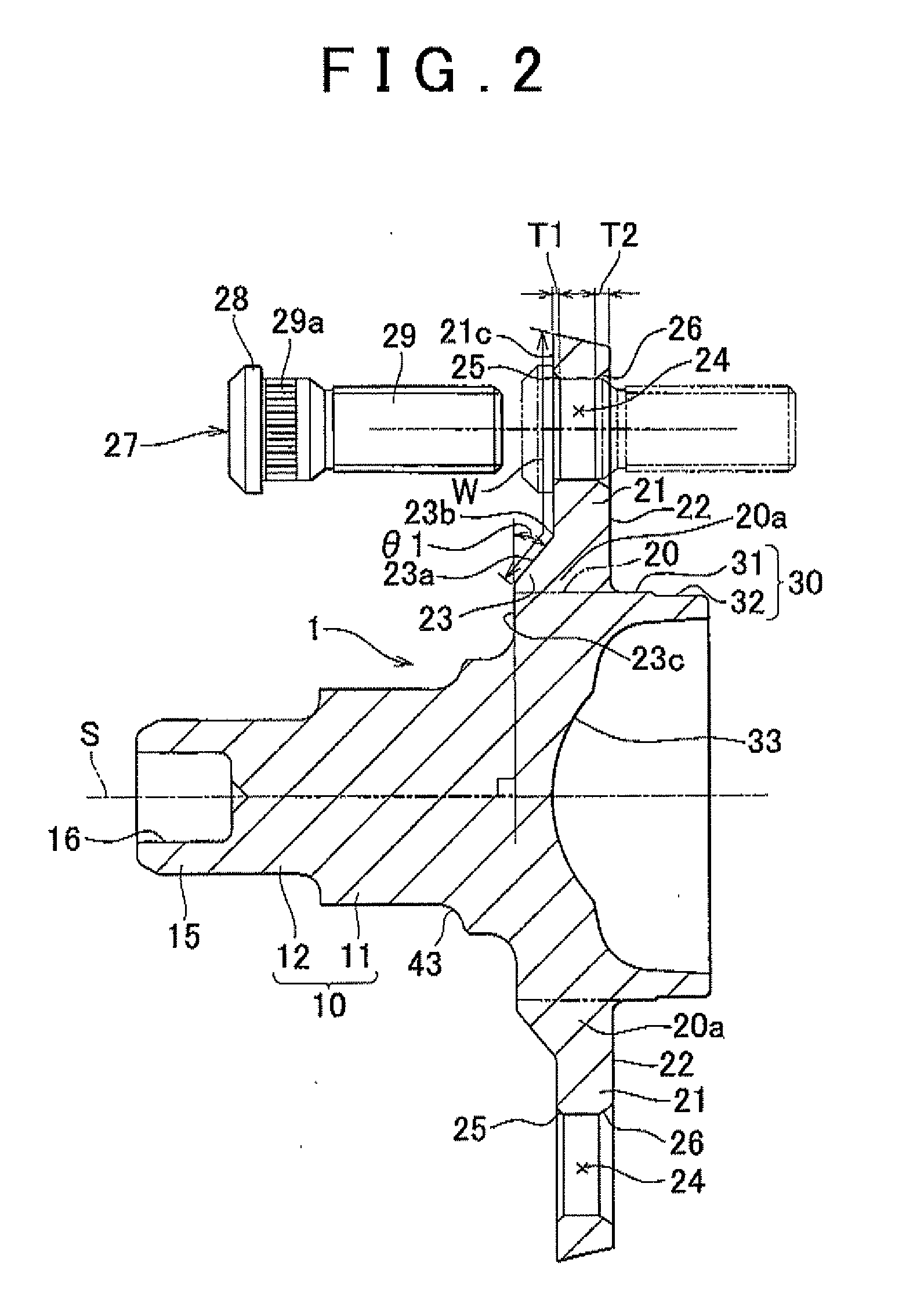
[0043]First, a wheel bearing device according to a first embodiment of the invention will be described with reference to FIG. 1 to FIG. 3.
[0044]As shown in FIG. 1, a wheel hub unit includes a unit of a flanged shaft member (hub wheel) 1 and a double row angular contact ball bearing 41. The wheel hub unit serves as the wheel bearing device. The double row angular contact ball bearing 41 serves as a rolling bearing.
[0045]The flanged shaft member 1 integrally includes a shaft portion 10, a fitting shaft portion 30, a flange proximal portion 20a and a plurality of flange portions 21. The double row angular contact ball bearing 41, which serves as the rolling bearing, is assembled onto the outer peripheral surface of the shaft portion 10. The fitting shaft portion 30 is formed on one end side of the shaft portion 10 and has a larger diameter than that of the shaft portion 10. The fitting shaft portion 30 is fitted to a center hole of a wheel (not shown). The flange proximal portion 20a i...
second embodiment
[0098]Next, a wheel bearing device according to a second embodiment of the invention will be described with reference to FIG. 10 and FIG. 11.
[0099]As shown in FIG. 10, in the second embodiment as well, a plurality of flange portions 121 of a flanged shaft member 101 are formed by side extrusion when a forged recess 133 is formed at the center of the end surface of a fitting shaft portion 130 by cold forging.
[0100]As shown in FIG. 11, in the second embodiment, each flange portion 121 is formed so that both side portions 121g are thinner than a widthwise center portion 121f in the cross-sectional shape taken perpendicularly to the longitudinal direction. In addition, edge portions 121e of the cross-sectional shape of each flange portion 121 are formed in an R-chamfered shape.
[0101]The other configuration of the second embodiment is similar to that of the first embodiment, so the description thereof may be omitted where appropriate. This also applies to the embodiments described later....
third embodiment
[0111]Next, a wheel bearing device according to a third embodiment of the invention will be described with reference to FIG. 13 and FIG. 14.
[0112]As shown in FIG. 13, a seal sliding portion 57 is molded by cold forging with predetermined accuracy. In addition, the seal sliding portion 57 is formed of a bonderlube-treated film or a molybdenum disulfide film so that the coefficient of friction of the surface is low.
[0113]In addition, the characteristic of the area of the flange portions 21 and the flange proximal portion 20a in the third embodiment as viewed in the axial direction will be described. The shaded portion in FIG. 14 indicates a region in which the first molding die 71 contacts the second molding die 72 within a region of an outside diameter circle to which the flange portions 21 are extended in the secondary molding of cold forging. In other words, the shaded portion is a portion, by which the flange portions 21 are lightened.
[0114]Here, where the outside diameter of each...
PUM
| Property | Measurement | Unit |
|---|---|---|
| Thickness | aaaaa | aaaaa |
| Diameter | aaaaa | aaaaa |
Abstract
Description
Claims
Application Information
 - R&D
- Intellectual Property
- Life Sciences
- Materials
- Tech Scout
- Unparalleled Data Quality
- Higher Quality Content
- 60% Fewer Hallucinations
Browse by: Latest US Patents, China's latest patents, Technical Efficacy Thesaurus, Application Domain, Technology Topic, Popular Technical Reports.
© 2025 PatSnap. All rights reserved.Legal|Privacy policy|Modern Slavery Act Transparency Statement|Sitemap|About US| Contact US: help@patsnap.com


