Device and method for dental cavity treatment

a technology for dental cavities and devices, applied in the field of devices and methods for treating dental cavities, can solve the problems of high fluid toxicity, difficult to remove bacterial films, and ineffective removal and disinfection procedures

Active Publication Date: 2010-08-19
MDT MICRO DIAMOND TECH LTD
View PDF19 Cites 37 Cited by
  • Summary
  • Abstract
  • Description
  • Claims
  • Application Information

AI Technical Summary

Benefits of technology

[0014]Optionally, said first electrode is controllably extendable along said axial direction, thereby to vary a length of a gap between said first electrode and said second electrode.

Problems solved by technology

Removal and disinfection procedures are not always effective at removing individual bacteria, but it is even more difficult to remove bacterial films.
Known systems insert cleaning (disinfecting) fluids into the root canal but such fluids are highly toxic.
Furthermore they have to be present in the root canal for a relatively large amount of time.
In addition the fluid must reach every part of the root canal, something which cannot be guaranteed.
A further disadvantage of the above system is that bubbles or air pockets tend to occur, especially in the deeper parts of the root canal or where root canal passages are not straight, and the air pockets tend to prevent the cleaning fluid from making contact with all surfaces.
The electromagnetic field and in some case the temperature kills bacteria, but the effectiveness is limited because often the conditions in the canal are not ideal.
A disadvantage of this system is that much of the power provided goes to setting up the current path and not to carrying out the sterilization.
Furthermore the sterilization effect is not uniform over the root canal, and requires exceptional skill on the part of the dentist in order to be successful.
Furthermore the resistance provided by the human body varies between individuals, making it impossible to control the power level in given cases.
Thus a higher than designed resistance may reduce the output and vice versa.
Furthermore the power increases with proximity to the apical aria, due to the reduced distance between the two ends of the probe or electrode and in some cases a current overload may result, causing pain to the patient.
Thus it is impossible to control the power and you may either expose the client to sharp, pain or you may fail to provide sufficient power to destroy all the bacteria.
In particular, efforts to ensure that the effect is evenly distributed over the root canal are complicated by the need to avoid the root canal apex.

Method used


Image

  • Device and method for dental cavity treatment
  • Device and method for dental cavity treatment
  • Device and method for dental cavity treatment

Examples


Embodiment Construction

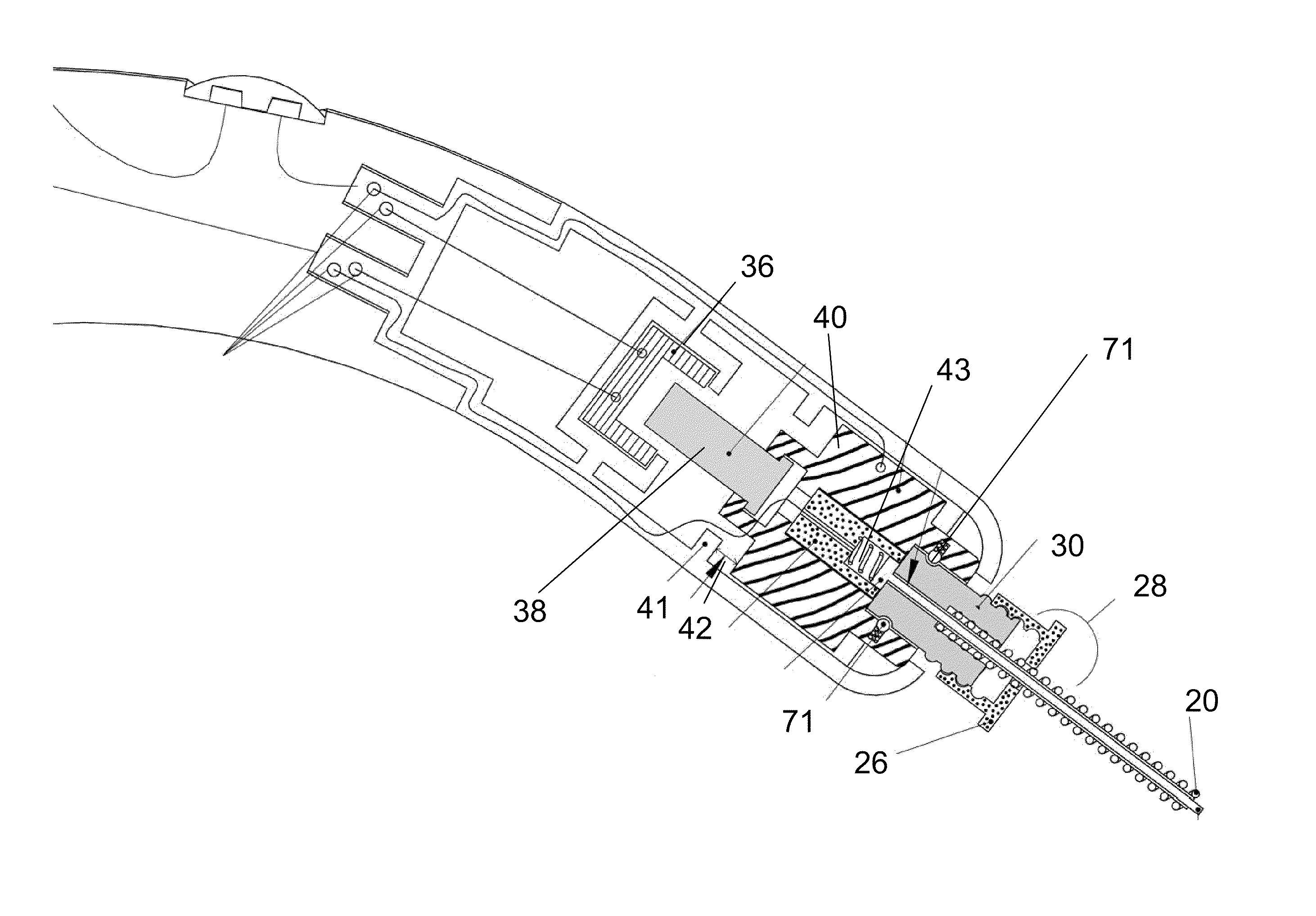
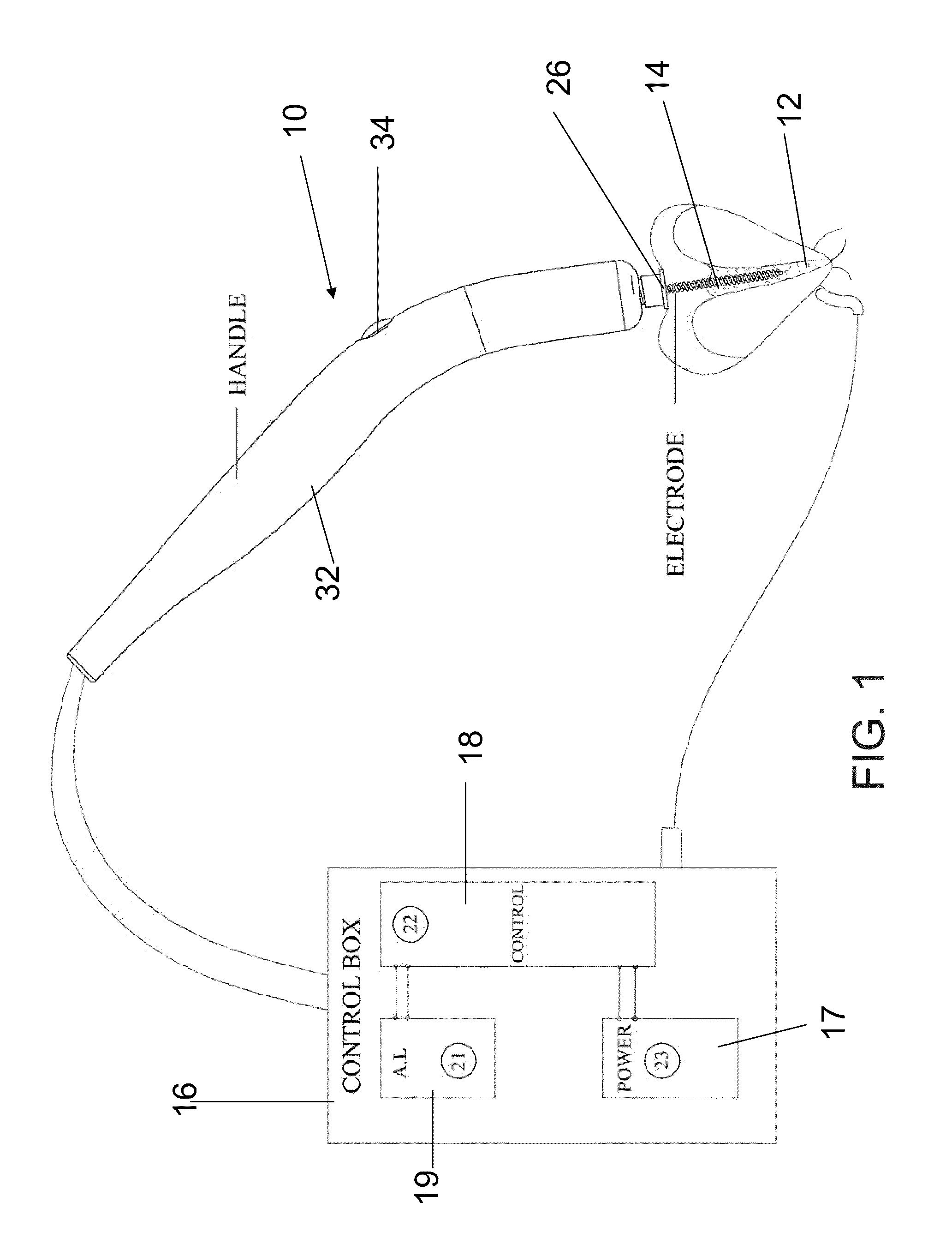
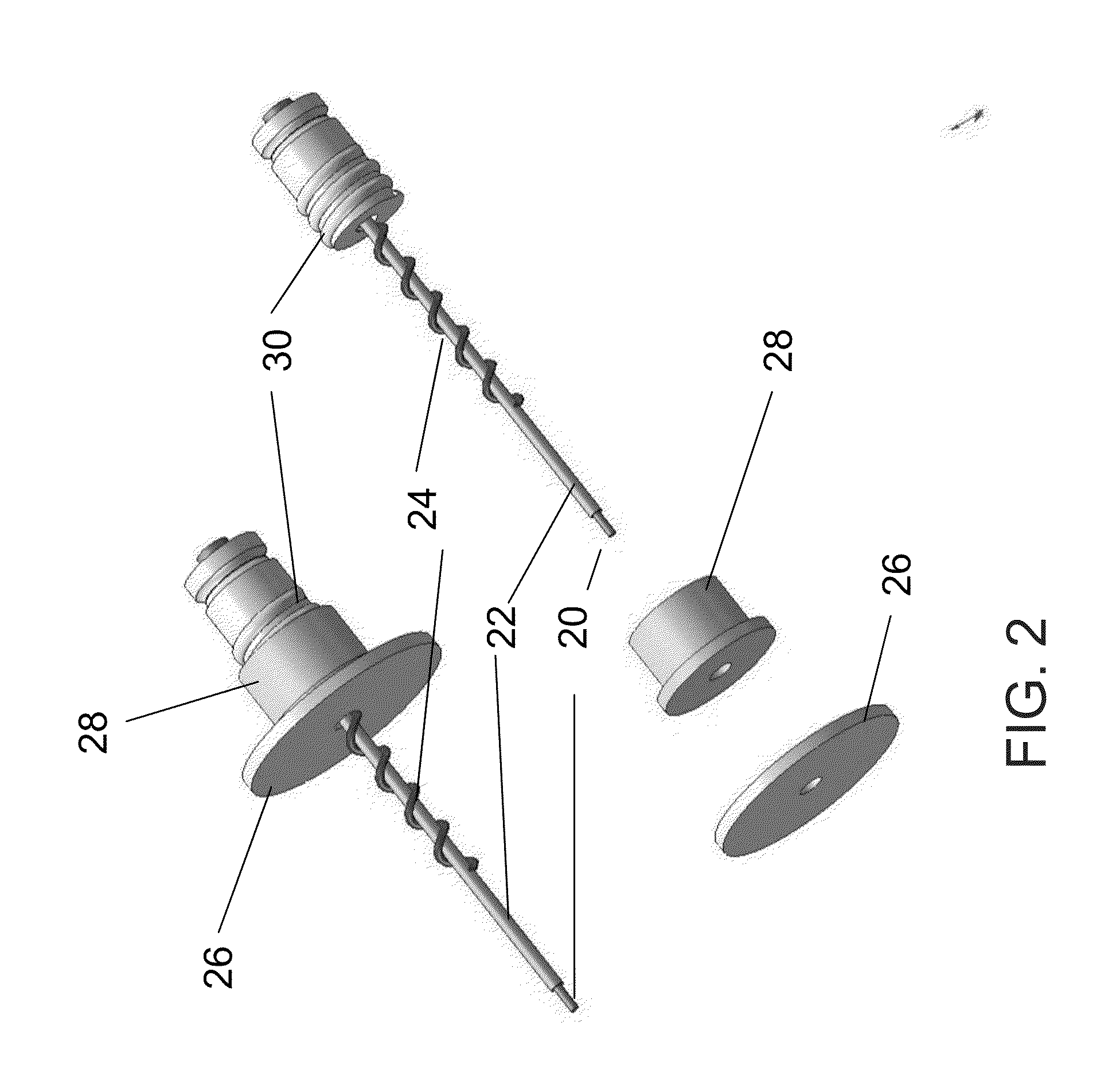
[0048]The present embodiments comprise an apparatus and a method for root canal sterilization using electrical energy, where an electrode pair is inserted into the root canal. A discharge is induced between the electrodes of the electrode pair. The current is confined to the root canal, and electrical energy is therefore kept out of surrounding tissues. The result is that several Joules of energy can be released within the root canal to kill the bacteria, without detrimental effect on the human body

[0049]The effect can be enhanced by filling the root canal with either a conductive fluid, such as salt water or an irrigation fluid such as 17% ethylenediaminetetraacetic acid (EDTA), to take two examples. Other fluids with high conductivity and / or sterilizing or disinfecting ability may also be considered. Mixtures of conducting materials and sterilizing or disinfection agents may also be used. In an embodiment of the invention a conductive fluid is placed in the root canal and the elec...


PUM


Abstract

A device for disinfecting and/or sterilization of a dental cavity comprising:
    • an electrode pair adapted to extend into said cavity to provide current along at least a portion of the cavity; and
    • a controller configured for sending controlled electrical energy to said cavity via current flowing between the electrodes when located in said cavity, thereby to provide electrical energy for said disinfection and/or sterilization.

Description

RELATED APPLICATION / S[0001]This application is a continuation-in-part (CIP) of PCT Patent Application No. PCT / IL2009 / 001048 filed Nov. 5, 2009, which claims the benefit of priority of U.S. Provisional Patent Application No. 61 / 193,204 filed Nov. 5, 2008. The content of both these applications are incorporated herein by reference.FIELD AND BACKGROUND OF THE INVENTION[0002]The present invention relates to a device and method for treatment of a dental cavity such as a root canal and, more particularly, but not exclusively to a device for sterilizing a root canal.[0003]A root canal is the commonly used term for the main canals within the dentine of the tooth. These are part of the natural cavity within a tooth that consists of the dental pulp chamber, the main canals, and sometimes more intricate anatomical branches that may connect the root canals to each other or to the root surface of the tooth. Root canals are filled with a highly vascularized, loose connective tissue, the dental pu...

Claims


Application Information

Patent Timeline
Patent Type & Authority Applications(United States)
IPC IPC(8): A61C19/06
CPCA61B18/14A61C5/02A61C19/042A61C5/04A61C19/041A61C5/025A61C5/40A61C5/44A61C5/50A61N1/0548A61N1/325
Inventor BECKER, ARIKROZENBOIM, HAIMLEVY, HAIMROTHENSTEIN, SIMONBERDICHEVSKY, GREGORYZEHARHARY, OMER
Owner MDT MICRO DIAMOND TECH LTD
Why Eureka
Try Eureka