Method and apparatus for comprehensive energy measurement and analysis of a building

a comprehensive energy measurement and analysis technology, applied in the direction of electric power measurement, mechanical power/torque control, electric devices, etc., can solve the problems of inefficient equipment, inability to fully benefit the occupant of the building, and insufficient consideration of inefficient equipment in the prior art, so as to reduce consumption without affecting the lifestyle or the comfort of the occupant, and reduce heat loss. , the effect of reducing the cos

Inactive Publication Date: 2010-08-19
GHOSN MICHEL
View PDF10 Cites 158 Cited by
  • Summary
  • Abstract
  • Description
  • Claims
  • Application Information

AI Technical Summary

Benefits of technology

[0022]The present invention is a system, method, and apparatus to provide a low cost, simple, and comprehensive analysis of the energy usage and parameters of a building. The invention involves: (a) collecting and analyzing the occupant pattern's habit of electricity usage to reduce consumption without affecting the lifestyle or the comfort of the occupant; (b) collecting and analyzing the temperature from inside and outside the building to quantitatively measure the thermal characteristics of the building (composite heat transfer coefficient and specific heat capacity) to indicate the corrective actions leading to a reduction heat loss and therefore reduce energy cost; and (c) collecting and analyzing the electricity consumption of all area lines connecting to the main electric panel of the building so as to identify: i) abnormal operations such as an inadequate heating or cooling system, unexpected cycling of an appliance such as a refrigerator, a near-tripping overloaded electric breaker; and ii) optimum areas candidate to be supplied by an alternative source of electrical energy with the least amount of electricity storage units.

Problems solved by technology

A problem associated with prior art is that prior art does not account for inefficient equipment.
For example, it is not a complete benefit for an occupant of a building to switch electricity providers while using largely inefficient equipment that counterbalances any cost savings generating by switching to the new provider.
Another problem associated with prior art is that prior art does not account for the thermal characteristics of the building itself.
For example, it is not a complete benefit for the occupant of a building to improve the controls of the heating and cooling system(s) while ignoring the heat loss / gain through the building shell / foundations.
Another problem associated with prior art is that prior art does not account for inefficient equipment that performs ideally.
For example, a specialized electronic apparatus that records the mechanical and electrical operation characteristics of heating and cooling equipment to determine the performance of the equipment based on predefined ideal performance charts is not a complete benefit for the occupant of a building if the performance of the equipment conforms to the predefined ideal performance while the equipment is undersized for the task required in the building, resulting in an overload of the equipment and an ultimate increase in the total cost of ownership of the equipment because of increased risk of failure and repair of said equipment.
All the previous art attempts fail to provide comprehensive analysis reports correlating the electricity consumption with the occupant usage habits of electrical energy and with the thermal characteristics for building and enclosed structures to form an overall button line cost savings for the occupants.

Method used


Image

  • Method and apparatus for comprehensive energy measurement and analysis of a building
  • Method and apparatus for comprehensive energy measurement and analysis of a building
  • Method and apparatus for comprehensive energy measurement and analysis of a building

Examples


Embodiment Construction

)

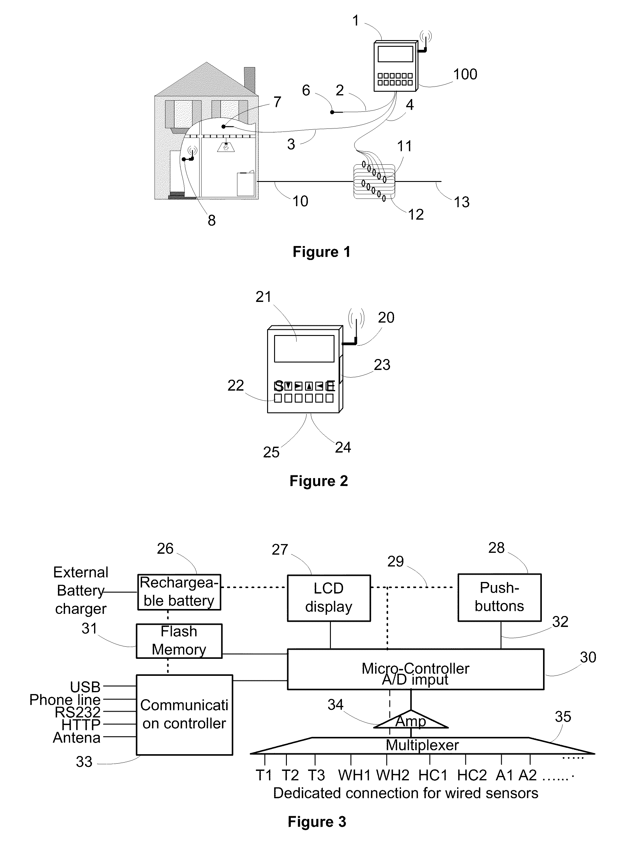
[0051]Referring to FIG. 1, there is shown a schematic diagram of a preferred embodiment of the disclosed system 100. The system 100 has a logging unit 1 connected to temperature sensors 6, 7, 8 and current sensors 11. The logging unit 1 collects, stores, and transmits the readings of the sensors 6, 7, 8, and 11. In FIG. 1, the logging unit 1 is an electronic apparatus that connects to temperature sensor 6 over wire 2 to measure the temperature outside building 9. The logging unit 1 connects to temperature sensor 7 over wire 3 to measure the inside temperature. The logging unit 1 connects to temperature sensor 8 over wireless radio to measure the temperature inside building 9. The logging unit 1 connects to current sensors 11 over wire 4 to measure, in non-invasive mode, the electric current running in each wire feed 12 of the main power supply line 10 the building structure 9. The wire feed 12 is also connected to the electric power line 13 of an electricity provider. Generally, ea...


PUM

PropertyMeasurementUnit
comprehensive energyaaaaaaaaaa
thermal characteristicaaaaaaaaaa
energy usageaaaaaaaaaa

Abstract

An energy monitoring and analysis system for a building includes a logging unit, a processing unit, temperature sensors that read the temperatures inside and outside the building, electric current sensors that read electric currents in all independent electric connections at the main connection panel of the building, and other types of sensors such as those related to natural gas flow. The logging unit periodically collects the data from all the sensors and transmits the data to the processing unit. The processing unit analyzes the data using highly sophisticated algorithms, extracts various parameters, profiles the electric energy usage, identifies potential problems with energy transfer and use, and lists recommendations for corrective actions. The processing unit analyzes data of the building, an HVAC system associated with the building, and consuming devices associated with the building.

Description

CROSS-REFERENCE TO RELATED APPLICATIONS[0001]The present application claims priority to U.S. Provisional Application No. 61 / 153,877, filed by the present inventor on Feb. 19, 2009.STATEMENT REGARDING FEDERALLY SPONSORED RESEARCH OR DEVELOPMENT[0002]Not applicable.NAMES OF PARTIES TO A JOINT RESEARCH AGREEMENT[0003]Not applicable.REFERENCE TO AN APPENDIX SUBMITTED ON COMPACT DISC[0004]Not applicable.BACKGROUND OF THE INVENTION[0005]1. Field of the Invention[0006]The disclosed method and apparatus relate to the energy efficiency of buildings. Particularly, the disclosed apparatus and method relate to the recordation, calculation, and communication of the energy efficiency of the construction of the building, the HVAC system of the building, the electrical equipment in the building, and the usage of the building and equipment by occupants of the building.[0007]2. Description of Related Art[0008]Buildings consume energy based on the activities of occupants thereof, who determine the ext...

Claims


Application Information

Patent Timeline
Patent Type & Authority Applications(United States)
IPC IPC(8): G06F1/32G05D23/19G01R21/00G01K13/00G01R19/00G06F19/00
CPCG01D4/002G01K17/00G01K2201/00Y04S20/32Y02B70/3275Y02B90/241Y04S20/244Y04S20/46G01D2204/18Y02B70/30Y02B90/20Y04S20/30
Inventor GHOSN, MICHEL
Owner GHOSN MICHEL
Why Eureka
Try Eureka