Control device for internal combustion engine

Inactive Publication Date: 2010-08-19
TOYOTA JIDOSHA KK
View PDF8 Cites 64 Cited by
  • Summary
  • Abstract
  • Description
  • Claims
  • Application Information

AI Technical Summary

Benefits of technology

[0015]The first aspect of the present invention makes it possible to incorporate the influence of EGR on torque into a target torque by determining a correction factor in accordance with a target EGR rate and an air amount and correcting the target torque with the correction factor. When a target air amount is calculated from the target torque into which the influence of EGR on torque is incorporated, and the operation of each actuator is controlled in accordance with the target air amount and the target EGR rate, the target torque can be achieved with high accuracy and without being affected by EGR.
[0016]The second aspect of the present invention makes it possible to provide accurate torque control without increasing the computational load on the control device by preparing a map that defines, on an individual. EGR rate basis, the relationship between the air amount and a rate of torque decrease due to the introduction of EGR.
[0017]As the target air amount is c

Problems solved by technology

Therefore, the target torque may not be accurately

Method used


Image

  • Control device for internal combustion engine
  • Control device for internal combustion engine
  • Control device for internal combustion engine

Examples


first embodiment

[0039]A first embodiment of the present invention will now be described with reference to the accompanying drawings.

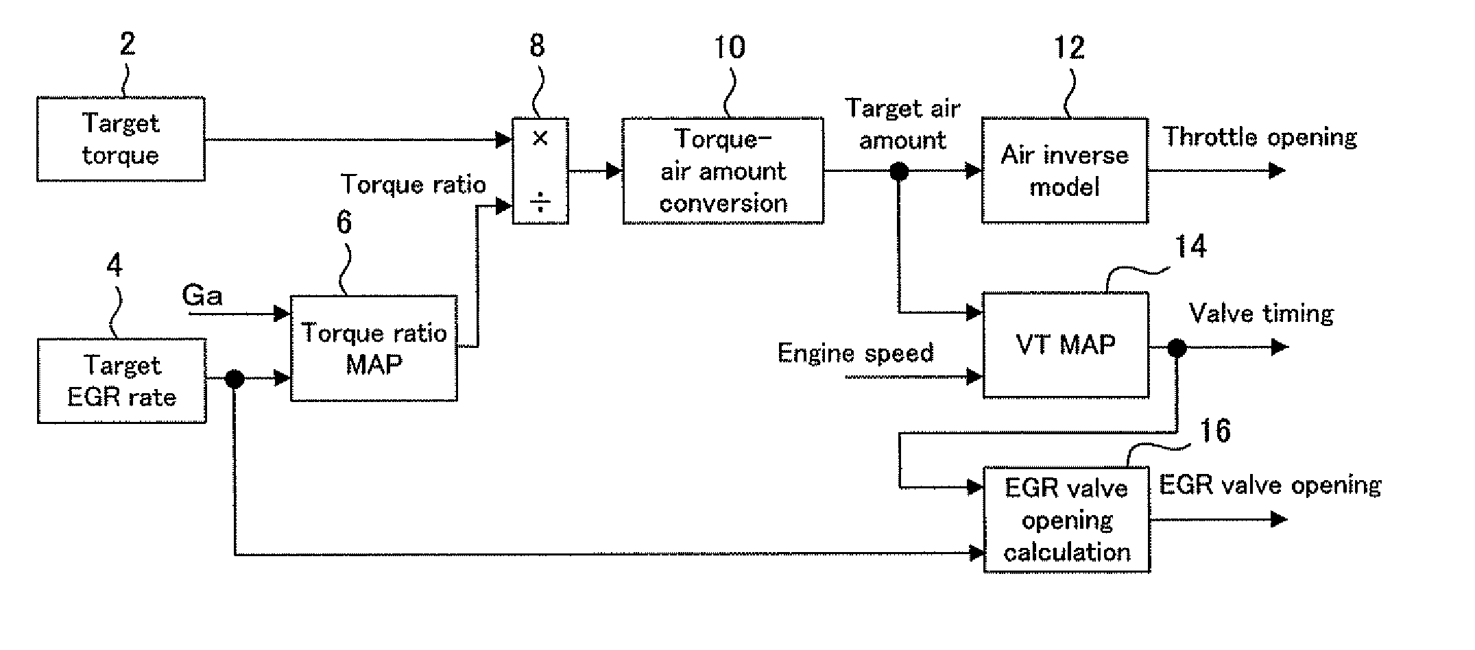
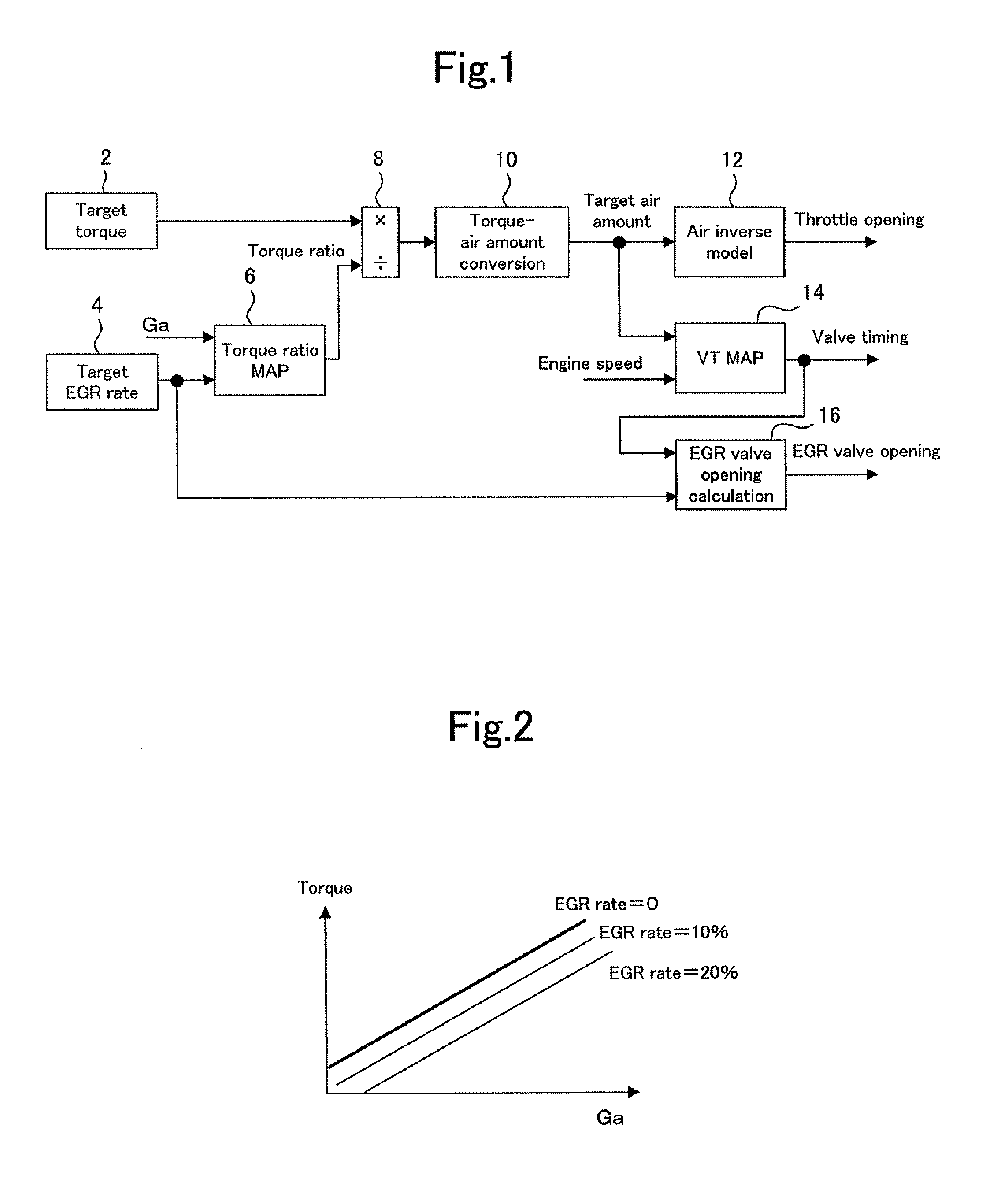
[0040]FIG. 1 is a block diagram illustrating the configuration of an internal combustion engine control device according to the first embodiment of the present invention. The control device according to the present embodiment is applicable to an internal combustion engine having at least a throttle, a variable valve timing mechanism (hereinafter referred to as the VVT mechanism), and an EGR valve, and configured as a device for controlling the operations of such actuators. It is assumed that the VVT mechanism is provided each for an intake valve and an exhaust valve. The EGR valve is mounted on an EGR pipe, which bypasses a cylinder and connects an intake pipe and an exhaust pipe. The configuration of the control device according to the present embodiment is described below with reference to FIG. 1.

[0041]The control device according to the present embodiment includes a...

second embodiment

[0062]A second embodiment of the present invention will now be described with reference to an accompanying drawing.

[0063]FIG. 5 is a block diagram illustrating the configuration of an internal combustion engine control device according to the second embodiment of the present invention. The control device according to the present embodiment is based on a control structure according to the first embodiment. In the control structure employed by the control device according to the present embodiment, however, an ignition device and a fuel injection device are additionally handled as control targets. More specifically, the control structure shown in FIG. 5 assumes that the throttle, VVT mechanism, EGR valve, ignition device, and fuel injection device are the actuators to be controlled. All these actuators are coordinately controlled in a single control structure. The configuration of the control device according to the present embodiment will be described below with reference to FIG. 5. ...


PUM


Abstract

The present invention provides a control device that is used with an internal combustion engine and capable of achieving a target torque with high accuracy and without being affected by EGR. A target torque setup device sets a target torque for the internal combustion engine. A target EGR rate setup device sets a target EGR rate. A target torque correction device and calculates a correction factor for correcting the influence of EGR on torque in accordance with the target EGR rate and an air amount, and corrects the target torque with the correction factor. A target air amount calculation device calculates a target air amount from the corrected target torque. A controller controls the operations of a plurality of actuators for adjusting an in-cylinder air amount and EGR rate in accordance with the target air amount calculated from the corrected target torque and with the target EGR rate.

Description

TECHNICAL FIELD[0001]The present invention relates to a control device for an internal combustion engine, and more particularly to an internal combustion engine control device that adjusts an in-cylinder air amount and an EGR rate by causing a plurality of actuators to coordinate with each other.BACKGROUND ART[0002]It is conventionally known that torque demand control is exercised to preselect a target torque for an internal combustion engine and achieve the target torque by regulating the operation of each actuator. A technology for exercising such torque demand control is disclosed in JP-A-2002-357147 and used to achieve both a target excess air ratio and a target torque in a region where torque is nonlinear with respect to an excess air ratio.[0003]The technology disclosed in JP-A-2002-357147 corrects the nonlinearity of torque with respect to the excess air ratio by calculating a torque correction factor in accordance with the target excess air ratio and correcting a target air ...

Claims


Application Information

Patent Timeline
IPC IPC(8): F02D41/00
CPCF02D11/105F02D21/08F02D41/005F02D41/006Y02T10/47F02D2041/0017F02D2200/0402F02D2250/18F02D41/0065Y02T10/40
Inventor SOEJIMA, SHINICHI
Owner TOYOTA JIDOSHA KK
Why Eureka
Try Eureka