Method and Apparatus for Forming the Calibration Chart for the Underground Fuel Tanks

a fuel tank and calibration chart technology, applied in the direction of liquid/fluent solid measurement, machines/engines, instruments, etc., can solve the problems of inaccurate calibration chart of the tank, difficult and costly work, and the measurement of millimeter value will not yield the correct value in liters, so as to achieve faster calibration performance and shorten the time

Active Publication Date: 2010-08-26
ASIS OTOMASYON VE AKARYAKIT SISTEMLERI ANONIM SIRKETI
View PDF9 Cites 10 Cited by
  • Summary
  • Abstract
  • Description
  • Claims
  • Application Information

AI Technical Summary

Benefits of technology

[0026]Still another object of the invention is to propose a structure, which does not hinder for extended periods of time the operation of the liquid fuel station...

Problems solved by technology

Otherwise, the measured millimeter value will not yield the correct value in liters.
However, the chart is suitable for the ideal conditions and when the tank is placed underground, it deviates from said ideal conditions and the calibration chart of the tank becomes erroneous.
This is a difficult and costly work.
For this system, the equipment such as one or two fuel tankers and the fuel transfer pump are used in the station and it may take hours to complete the calibration for one tank.
Manual calibration is labor intensive and costly, in addition to its hindering the overall functioning of the station.
This situation leads to a high cost and a long duration of ti...

Method used


Image

  • Method and Apparatus for Forming the Calibration Chart for the Underground Fuel Tanks
  • Method and Apparatus for Forming the Calibration Chart for the Underground Fuel Tanks

Examples


Embodiment Construction

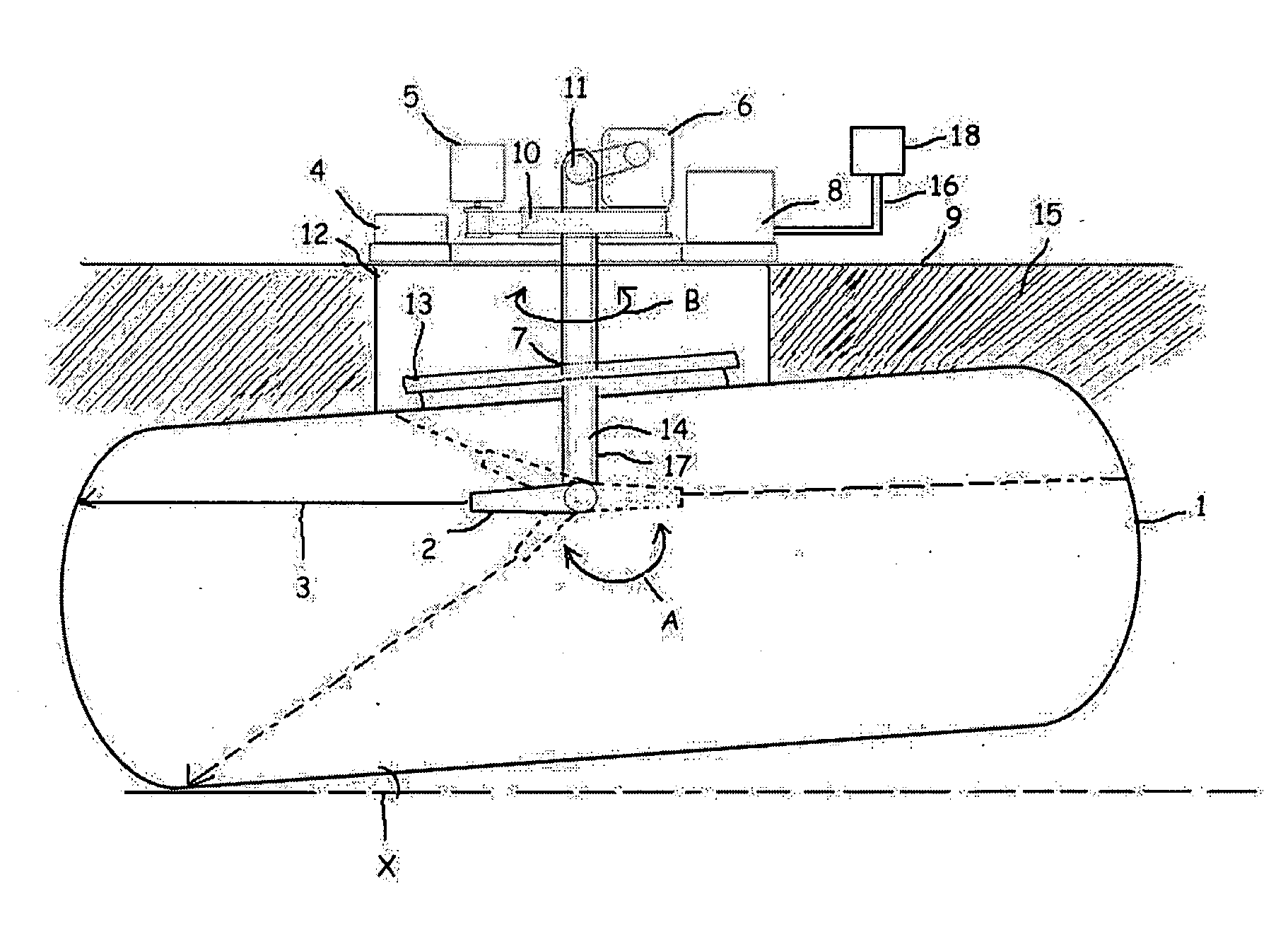
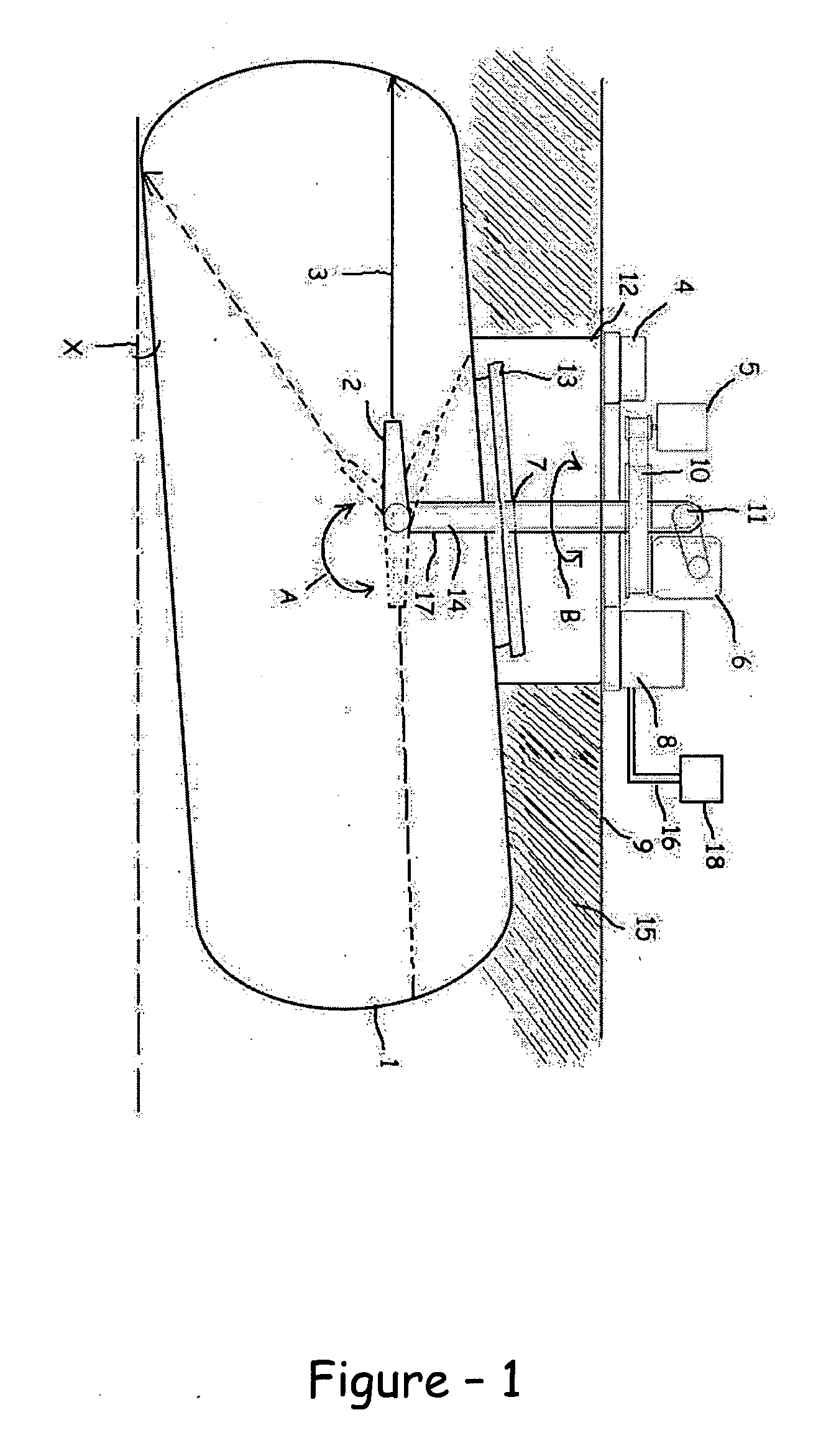
[0020]Based on the mentioned state of the art, the object of the invention is to propose a method, which, regardless of the angle at which the liquid fuel tank is placed on the ground, is capable of calibrating the actual value of the fuel amount inside the tank in a faster and more accurate manner as compared to the other systems.

[0021]Another object of the invention is to propose a structure, which provides a much more accurate and realistic calibration owing to the laser measurement instrument.

[0022]Another object of the invention is to propose a structure, which enables the calibration procedure to be carried out in a very short time and the calibration chart to be prepared easily.

[0023]Another object of the invention is to propose a structure with a much lower cost for the formation of the calibration chart.

[0024]Still another object of the invention is to provide that the calibration chart is prepared by means of the formation of the 3D (three dimensional) space points via las...


PUM


Abstract

The invention relates to the method and apparatus for forming the calibration chart used to measure the amount of fuel inside the fuel tanks (1) which comprises at least one laser distance measurement device (2) positioned inside said fuel tank (1) and measuring the distance between itself and the inner wall of said fuel tank (1) at separate points, at least one main shaft (14) providing said distance measurement device (2) with rotational movement circularly in the direction of B through up to 360 degrees and in the upward-downward direction of A through up to 270 degrees and at least one inclinometer (4) positioned on the surface (9) and measuring the angle X between said fuel tank (1) and the ground on which it is located.

Description

TECHNICAL FIELD[0001]The invention relates to the determination of the fuel level and amount inside the underground liquid fuel tanks in the gas stations.[0002]The invention relates in particular to forming the calibration charts used in order to determine the fuel level and amount inside the underground liquid fuel tanks in the gas stations, wherein the error margin is minimized.BACKGROUND OF THE INVENTION[0003]In the gas stations, various methods are employed to measure the level of oil inside the underground fuel tanks. Such methods may be carried out manually by dipping the level measurement sticks in the tank, as well as automatically with the help of the electronic measurement sensors placed into the tank.[0004]In all the said methods, the calculation is made for the amount of liters that the level measured in millimeters corresponds to. Said calculation is made using the calibration chart previously prepared for the fuel tank. The calibration chart shows the height of the fue...

Claims


Application Information

Patent Timeline
IPC IPC(8): G01F25/00
CPCG01F17/00G01F25/0084G01F25/0061G01F25/20
Inventor KAYA, YUSUF
Owner ASIS OTOMASYON VE AKARYAKIT SISTEMLERI ANONIM SIRKETI
Why Eureka
Try Eureka