
Oil-Sludge Filtration System With Aeration Pump

Active Publication Date: 2010-08-26
AIR & LIQUID SYST LLC
View PDF26 Cites 9 Cited by
  • Summary
  • Abstract
  • Description
  • Claims
  • Application Information

AI Technical Summary

Benefits of technology

[0011]A dissolved gas flotation arrangement having a fluid mixture source, a gas source and an aeration pump creates a dissolved gas mixture from the fluid mixture and gas received from the fluid mixture source is provided. The dissolved gas mixture is input to the consolidation tank through the micro-aeration inlet. A contaminate chute arrangement is connected to the consolidation tank and receiv

Problems solved by technology

The paint sludge and oil filtration systems discussed above often require large amounts of solution to be filtered.
Another problem that can occur is during system shutdowns back pressure in the recycling lines cause mixtures of solution and contaminate to backup into the contaminate tank; it is desirable to have a system that will continue to filter and remove the contaminate in the areas where the backup can occur in order to reduce the energy consumption of the pumps in the system.
Another issue that can be encountered is that existing systems often lack the ability to adapt to drastic changes in fluid levels in the various tanks or account for foam and other coagulated particles floating on the surface of the solution which can give false readings as to the actual fluid levels in the tanks.

Method used


Image

  • Oil-Sludge Filtration System With Aeration Pump
  • Oil-Sludge Filtration System With Aeration Pump
  • Oil-Sludge Filtration System With Aeration Pump

Examples


Embodiment Construction

[0026]The following description of the preferred embodiment(s) is merely exemplary in nature and is in no way intended to limit the invention, its application, or uses.

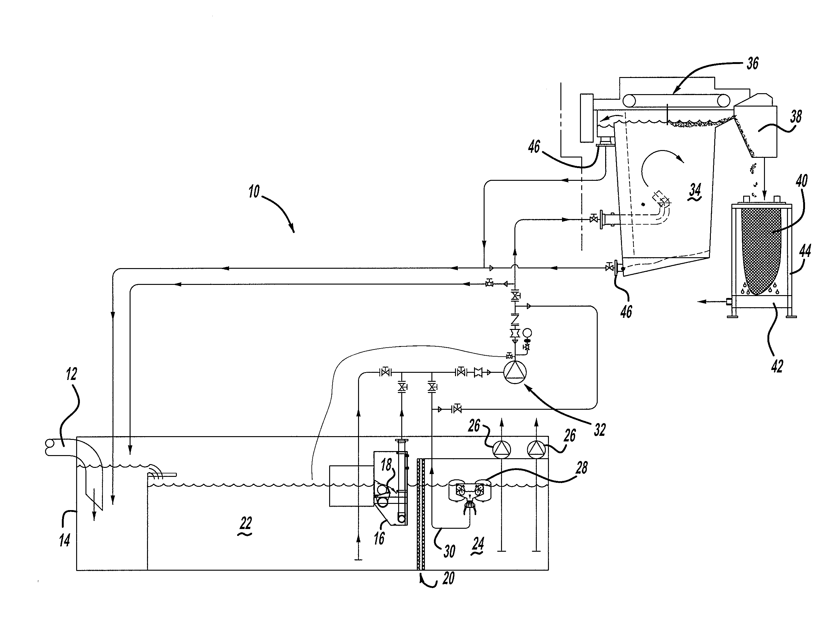
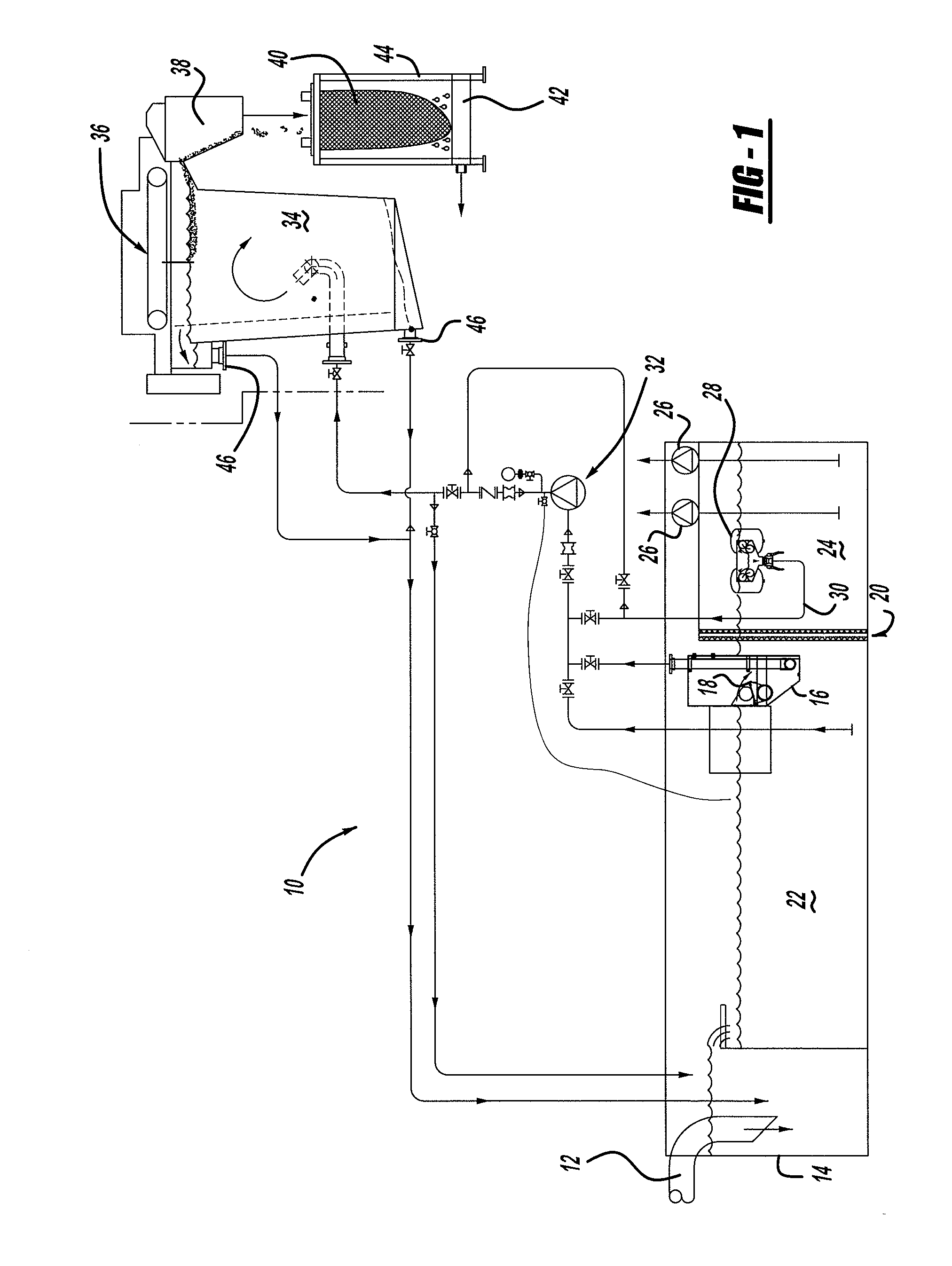
[0027]Referring to FIG. 1 a schematic diagram of a system 10 for consolidating and removing contaminate from a fluid mixture. The fluid mixture containing contaminate such as paint sludge particles or oils contained in a solution, such as water or a hydrophobic wash solution which together form a fluid mixture. The fluid mixture is obtained from the waterfall of a paint spray booth and / or a catch basin for spray painting or washing automotive parts. The waterfall and catch basin is channeled through an inlet pipe 12 or spray header that empties into a contaminate tank 14.

[0028]The contaminate tank 14 in this particular embodiment is quite large and can hold approximately 5,000 to 150,000 gallons. However, it is possible to a contaminate tank 14 of virtually any size to be used if needed. Within the contaminate tank 14...


PUM


Abstract

A system for consolidating and removing contaminate such as paint sludge or oils from a fluid mixture. A contaminate tank receives a supply of the fluid mixture containing contaminate from a source such as a manufacturing line where overspray of paints or cleaning solutions containing washed away oils are collected. A free floating weir floats on the surface of the contaminate tank and mechanically separates and removes contaminate from a surface of the contaminate tank and concentrates the contaminate in a consolidation tank. In the consolidation tanks the contaminate is further separated and collected for disposal.

Description

CROSS-REFERENCE TO RELATED APPLICATIONS[0001]This application is a continuation-in-part of U.S. Non-Provisional patent application Ser. No. 11 / 674,309 filed on Feb. 13, 2007.FIELD OF THE INVENTION[0002]The present invention relates to systems for filtering contaminate such as paint sludge and oil from a solution.BACKGROUND OF THE INVENTION[0003]During the manufacture of painted parts, such as automotive body parts industrial wastes are produced. By-products such as paint sludge particles and oils are produced and require proper disposal. Systems for concentrating, filtering and removing paint sludge particles and oils from mixtures derived from industrial solutions are necessary to meet environmental standards.[0004]A common technique for capturing paint overspray / airborne paint particulate produced when operating a paint spray booth is to capture the particulate in a waterfall backdrop within the spray booth. The resulting water-and-particulate fluid mixture is then channeled into ...

Claims


Application Information

Patent Timeline
IPC IPC(8): B01D17/032B01D17/035
CPCB01D21/0012B01D21/2433B01D21/26B01D21/267B05B15/1266B05B14/462Y02P70/10
Inventor URQUHART, GORDON T.MILLER, JAMES E.
Owner AIR & LIQUID SYST LLC
Learn More