Aeration device

a technology of aeration device and diffuser, which is applied in the direction of heating type, specific water treatment objectives, fuel gas production, etc., can solve the problems of slow rise of small bubble size in fine bubble diffuser, insufficient mixing of sewage in aeration tank, and consumption of aeration system in wastewater or sewage treatment plant providing very small bubble size, etc., to achieve slow mixing of liquid and high energy consumption

Inactive Publication Date: 2010-08-26
GRUNDFOS BIOBOOSTER
View PDF0 Cites 7 Cited by
  • Summary
  • Abstract
  • Description
  • Claims
  • Application Information

AI Technical Summary

Benefits of technology

[0006]It is an object of the invention to provide an aeration device that is arranged for providing small and very small air bubbles in a liquid. It is a further object of the present invention to provide a more efficient aeration device. It is yet a further object of the present invention to provide an alternative to the prior art. In particular, it may be seen as an object of the present invention to provide a aeration device that solves the above mentioned disadvantages of the prior art in relation to a high energy consumption and / or slow mixing of liquid and air bubbles.SUMMARY OF THE INVENTION
[0007]Thus, the above described object and several other objects are intended to be obtained in a first aspect of the invention by providing an aeration device for aeration of a liquid, comprising a plate of a first material, said first material being permeable to air, said plate having inlet means for inletting air into the plate; means for creating a flow of liquid across the plate of the first material, when said aeration devices is immersed or submerged in a liquid, wherein the plate is stationary within the aeration device. Air under pressure may be inlet into the plate via the inlet means and may exit the plate through the material which is permeable to air. The flow of liquid across the plate will cause the air permeated through the plate material to detach from the plate; this will provide smaller air bubbles compared with a plate across which no flow of liquid is provided. The size of the air bubbles detached from the plate will decrease with increasing flow across the plate. Thus, the size of the air bubbles created may be controlled.

Problems solved by technology

Even though very small bubble sizes, such as ultra fine bubbles in the micrometer size provides a large bubble surface area on which exchange may occur, such small bubble sizes in fine bubble diffusers rise quite slowly and do not provide adequate mixing of sewage in an aeration tank.
Moreover, the aeration system in a wastewater or sewage treatment plant providing very small bubble sizes may consume at between 50% and 70% of the energy of the entire plant.

Method used


Image

  • Aeration device
  • Aeration device
  • Aeration device

Examples


Embodiment Construction

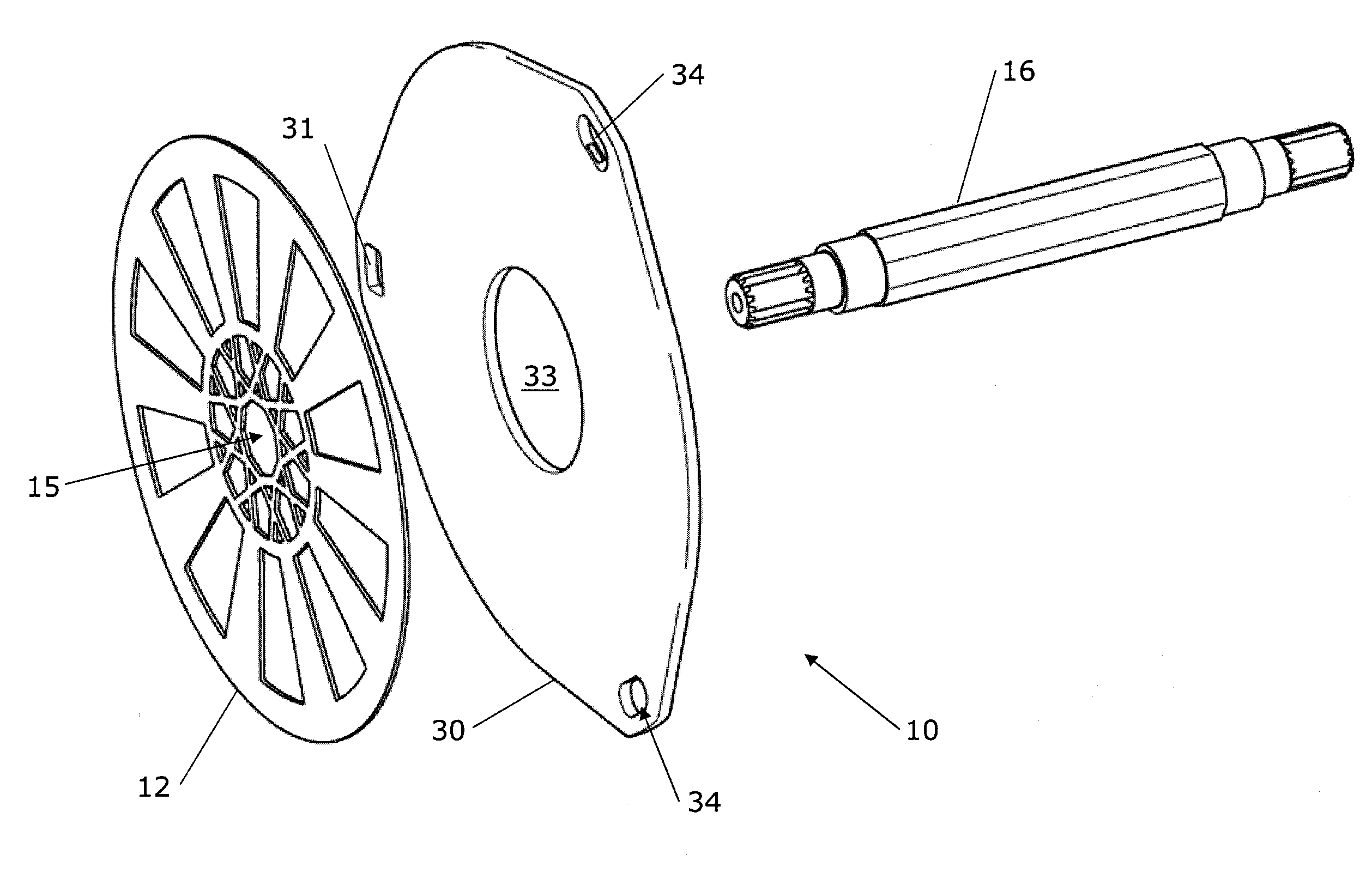
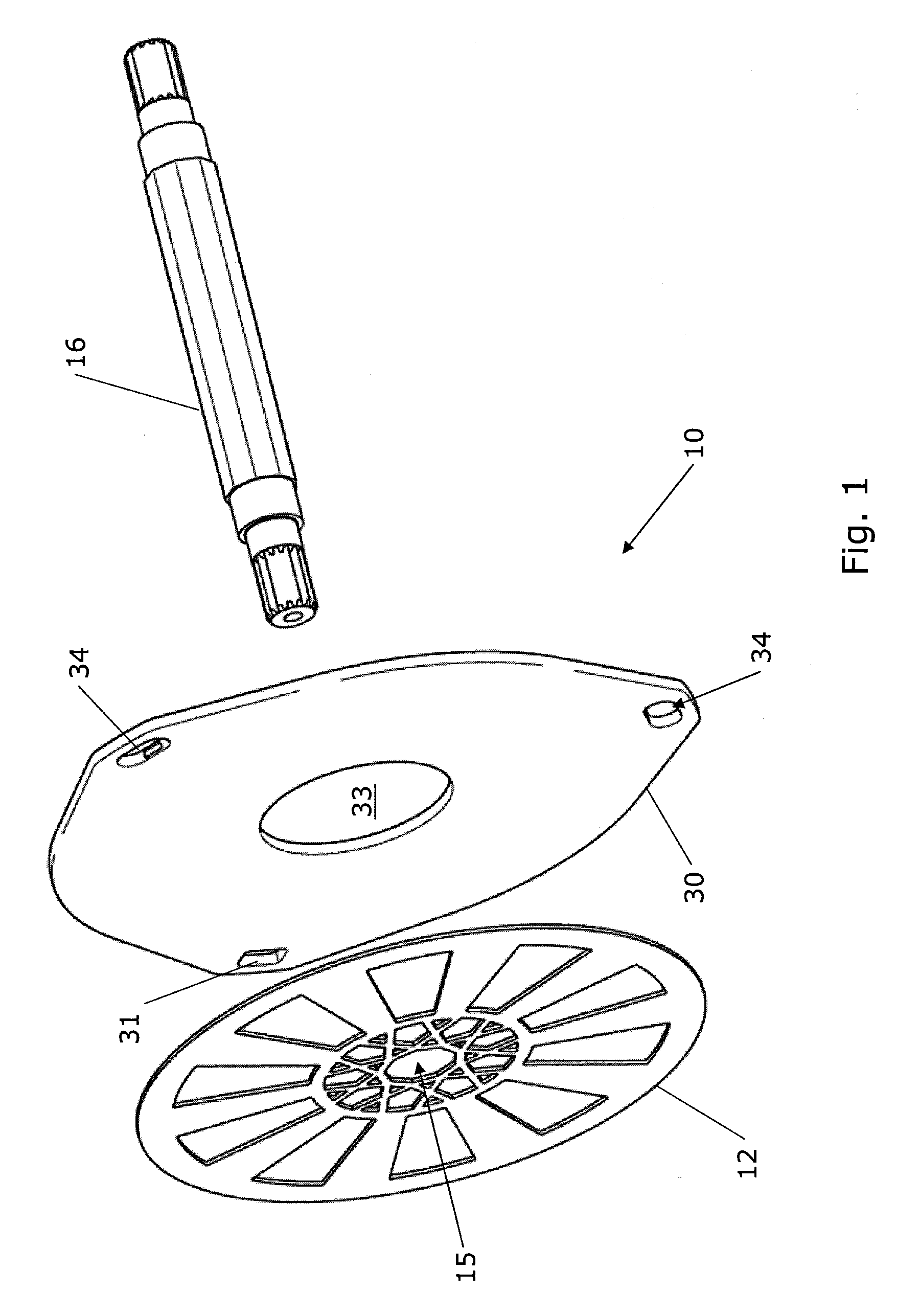
[0035]FIG. 1 shows an exemplary aeration device 10 of the invention in exploded view. Shown is a plate 30 of a first material, being permeable to air, for example a sintered material, such as ceramic material or a sintered metal material, or a polymer material. The polymer material may have chemically or otherwise formed pores of appropriate size in order to let an appropriate amount of air flow through it.

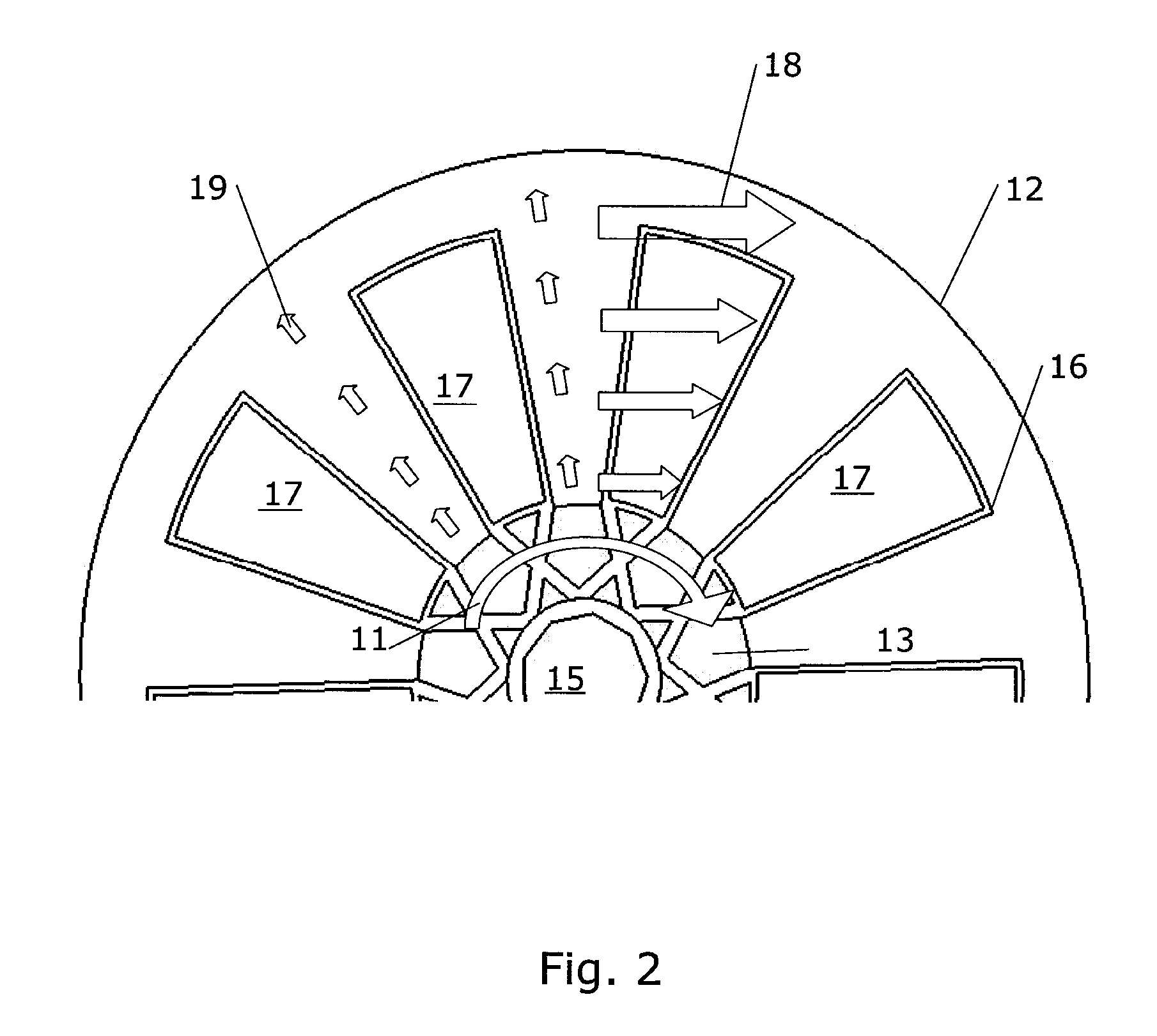
[0036]The plate 30 has a central hole 33 as well as openings 31, 34. One of the openings is an inlet 31 connected to a pattern of internal cavities within the plate 30 (see FIGS. 6b and 6c). Air may be input into the inlet 31 for distributing air within internal cavities of the plate 30. The wording “internal cavities” is meant to denote that the cavities lie within the material of the plate 30 and that, apart from a possible air connection by permeation through the first material of the plate, their only connection to the outside of the plate is a connection to the inlet 31 of th...


PUM

PropertyMeasurementUnit
pore sizeaaaaaaaaaa
pore sizeaaaaaaaaaa
pore sizeaaaaaaaaaa

Abstract

The invention relates to an aeration device (20) for aeration of a liquid. The aeration device comprises a plate (30) of a first material, said first material being permeable to air, said plate having inlet means (31) for inletting air into the plate and means for creating a flow of liquid across the plate of the first material, when said aeration device is immersed or submerged in a liquid. The plate of first material is stationary within the aeration device. The aeration device may moreover comprise a disc (12) arranged for being placed in parallel to the plate, but leaving a gap between the plate and the disc member, and the means for creating a flow of liquid across the plate of the first material may comprise means for rotating the disc member around a central axis through the disc member. Small or very small bubbles of air may be generated by the combination of air permeable material and creation of a flow across the plate.

Description

FIELD OF THE INVENTION[0001]The present invention relates to an aeration device for aeration of a liquid. The invention moreover relates to an aeration system comprising one or more aeration devices. Finally, the invention relates to a method for aerating a liquid and a use of the aeration device for aerating a liquid.BACKGROUND OF THE INVENTION[0002]Aeration is the process by which air is circulated through, mixed with or dissolved in a liquid or substance. Aeration of liquids may be advantageous in many types of systems, i.a. treatment of waste water, aerobic biological processes, cultivation of bacteria in liquids, etc. Aeration of liquids is typically achieved by passing the liquid through air by means of fountains, cascades, paddle-wheels or cones or by passing air through the liquid by means of a Venturi tube, aeration turbines or compressed air which can be combined with diffuser air stones, as well as fine bubble diffusers, coarse bubble diffusers or linear aeration tubing. ...

Claims


Application Information

Patent Timeline
Patent Type & Authority Applications(United States)
IPC IPC(8): B01F3/04
CPCB01F3/04262B01F3/04539B01F2003/0456C02F2303/20C02F3/1273C02F3/205B01F2003/04687Y02W10/10B01F23/23123B01F23/23313B01F23/2331B01F23/23364
Inventor MADSEN, STEFFEN
Owner GRUNDFOS BIOBOOSTER
Why Eureka
Try Eureka