
Battery-Cell Converter Management Systems

a technology of converter management and battery cells, applied in the direction of charging equalisation circuit, transportation and packaging, and arrangement of several simultaneous batteries, can solve the problems of battery cell damage, battery quickly dies out, battery damage, etc., and achieves the improvement of battery per charge use time, battery pack manufacturing cost, and battery pack li

Inactive Publication Date: 2010-08-26
TSE LAWRENCE TZE LEUNG
View PDF16 Cites 143 Cited by
  • Summary
  • Abstract
  • Description
  • Claims
  • Application Information

AI Technical Summary

Benefits of technology

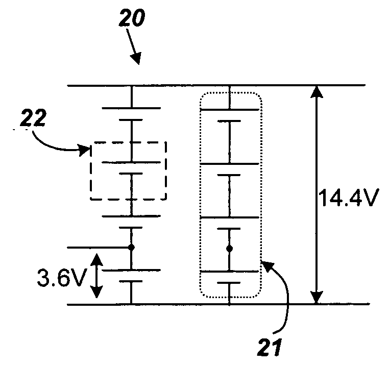
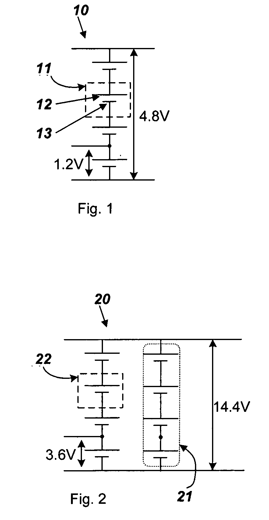
[0013]A new method of constructing a rechargeable battery unit is by exploring the advantages of the combined, integrated solution of power converters and charge-storing battery cells. This new topology improves battery per-charge use-time, battery pack life-time, and battery pack manufacturing cost by practically eliminating a) the need for special cell binning procedures during battery pack manufacturing to select better matched cells into a given battery pack, and b) the need for special cell balancing procedure during charging and / or discharging of battery packs (which also eliminates the external components such as Ls, Cs, or Rs needed for cell balancing operations). The new BCC architecture enables a multi-cell battery pack to continue to function substantially close to normal operation with the presence of badly degraded battery cells residing in the pack.

Problems solved by technology

At this moment, popular multi-cell rechargeable battery packs used in handheld appliances, computers, power tools, etc, are rather expensive and range from US$30 to US$300, depending on the number of cells and their respective capacity in the pack.
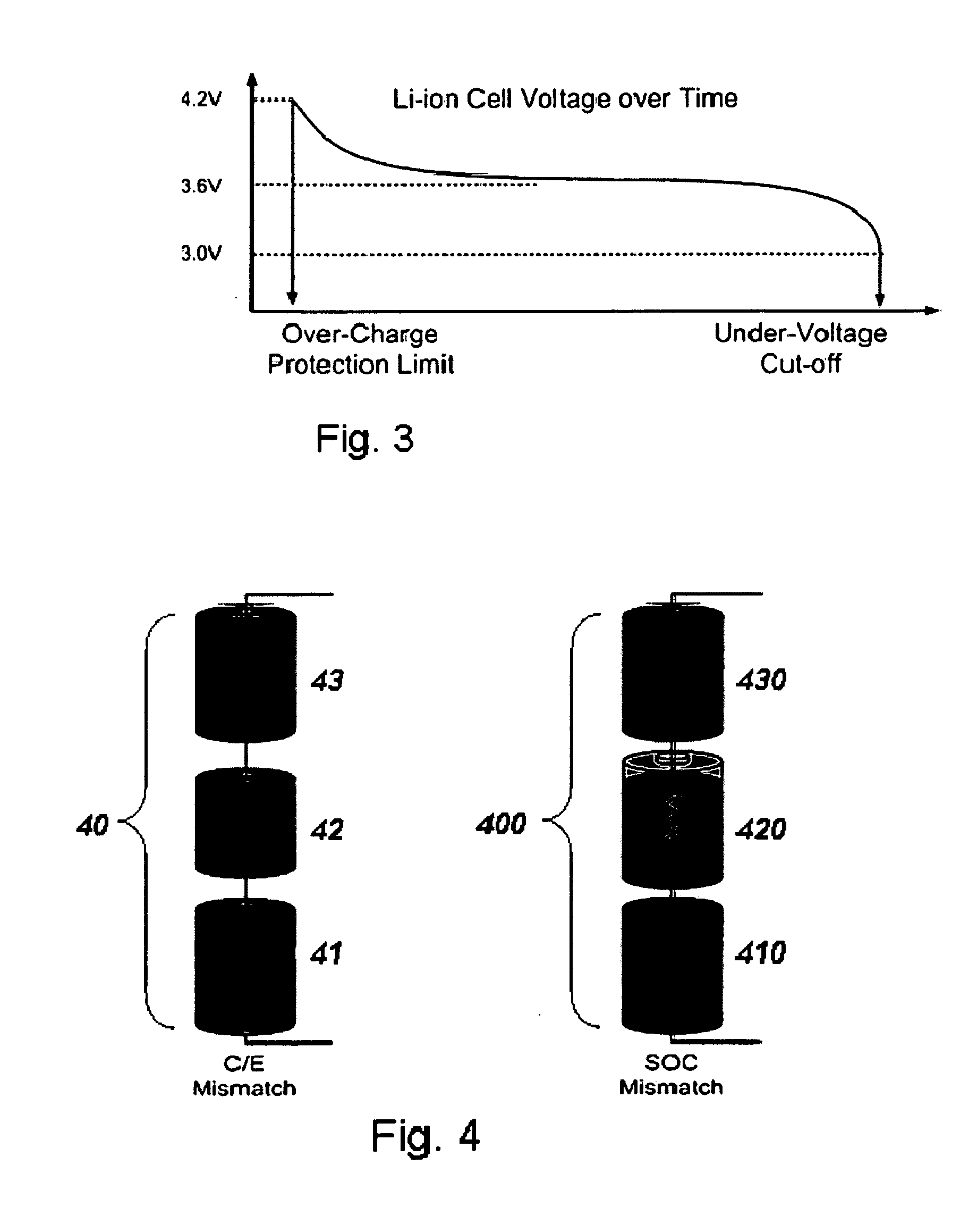
A battery cell can be damaged by excessively charged to a high voltage or excessively discharged to a low voltage.
After the battery discharges to about 2.7-3.0V, the battery quickly dies out and can also get damaged.
One of the key challenges in charging / discharging multi-cell battery units is related to the non-uniformity of battery cells within the pack due to manufacturing tolerances.
There is more than one type of battery cell mismatch.
A weakest battery cell tends to limit the overall capacity of the entire battery pack unit.
However, such an extra step increases manufacturing cost.
Moreover, mismatch between the cells increases after charge / discharge cycles which reduces the benefit of binning at the factory.
The factories that do not go through a costly binning process have the yields on their battery cells severely impacted.
Besides, disposal of out-of-spec cells can increase the pollution footprint of the manufacturing facility.
It is apparent that this binning step is a brute-force approach and can only partially mitigate cell mismatch issue since cell mismatches tend to get worse after multiple charge / discharge cycles.
As a result, mismatch degradations cannot be easily addressed during battery cell manufacturing and quality control.
In addition, a battery pack that includes a series of stacked battery cells will no longer be functional if any given cell in the stack is severely degraded, such as the case as shown in FIG. 4a.
In other words, the battery pack's life time is then cut short due to one single damaged cell.
Such charging control is more straightforward for a single battery cell, but is a complex task for a series string of battery cells when the cells are not well-matched.
Note that practical implementation of charge transfer type of battery cell balancing is typically limited to charge transfer to a neighboring cell, it is impractical to implement a matrix of charge transfer circuits that can allow any two cells to have a charge transfer path.
In addition, there are losses associated with charge balancing.
As an individual cell becomes defective, the whole chain of series-stacked cells cannot be used and the multi-cell battery unit capacity is immediately halved.

Method used


Image

  • Battery-Cell Converter Management Systems
  • Battery-Cell Converter Management Systems
  • Battery-Cell Converter Management Systems

Examples


Embodiment Construction

[0033]Disclosed herein in exemplary embodiments are a series of new system configurations and new methodologies which include the coupling of one or more DC / DC converters to one or more battery cells. These system configurations, herein referred to as Battery Cell Converters (BCC), provide a near constant voltage output or near constant multiple voltage outputs; the system topologies and algorithms also optimize the usage and reliability of individual battery cell as well as the battery pack system as a whole.

[0034]A block diagram of a multi-cell BCC system is shown in FIG. 5a. BCC unit 50a comprising one or more energy-storing battery cells 51a, one or more DC / DC converters 52a each having input and output terminals; terminals of the energy-storing battery cells are coupled to or integrate with input terminals of one or more of said DC / DC converters via 53a; There are one or more BCC system outputs (V1, V2, . . . ), which are also outputs of DC / DC converters; and a monitoring & con...


PUM


Abstract

A battery cell converter (BCC) unit including one or more energy-storing battery cells coupled to one or more DC / DC converters is disclosed. A management unit can monitor and control the charging and discharging of each battery cells; including monitoring of voltages & State-of-Charge of each cell as well as controlling the switching of the DC / DC converters. The combined power and cell switching algorithms optimizes the charging and discharging process of the battery cells. A compound battery cell converter system comprising a series stack of BCCs to achieve high effective converter output voltage is also disclosed. The new proposed Battery Cell Converter architecture will enable improvements in battery pack usage efficiencies, will increase battery pack useable time per charge, will extend battery pack life-time and will lower battery pack manufacturing cost.

Description

CROSS-REFERENCE TO RELATED APPLICATIONS[0001]This application claims priority to provisional U.S. application Ser. No. 61 / 208,304, filed on Feb. 23, 2009, the disclosure of which is fully incorporated in its entirety by reference herein.BACKGROUND OF INVENTION[0002]1. Field of Invention[0003]The present invention generally relates to systems and methods of constructing a battery unit out of a plurality of battery cells coupled to or integrated with a plurality of voltage / current converter units for rechargeable batteries.[0004]2. Description of Related Art[0005]With the growing requirements of high-energy battery-operated applications, the demand of multi-cell battery packs has been increasing drastically. Multi-cell is needed to serve the high capacity / energy requirements of certain battery applications. Within a multi-cell battery pack, there is usually more than one cell connected in series. For example, a battery pack with four 1.2-volt cells connected in series gives a nominal ...

Claims


Application Information

Patent Timeline
Patent Type & Authority Applications(United States)
IPC IPC(8): H02J7/00H02J7/02
CPCH02J7/0014H02J7/0013H02M3/1582
Inventor TSE, LAWRENCE TZE-LEUNG
Owner TSE LAWRENCE TZE LEUNG
Learn More