Analog-digital converter

a converter and analog technology, applied in the field of analog digital converters, can solve the problems of increasing circuit size, device breakdown, and current flow in the circuit, so as to and prevent device breakdown and occurrence of through curren

Inactive Publication Date: 2010-08-26
RENESAS ELECTRONICS CORP
View PDF4 Cites 6 Cited by
  • Summary
  • Abstract
  • Description
  • Claims
  • Application Information

AI Technical Summary

Benefits of technology

[0018]In the analog-digital converter having the above configuration, when the output voltage of the integrator reaches the first reference voltage, the reference voltage of the high-potential side comparator is reset to the second reference voltage. Further, when the output voltage of the integrator reaches the second reference voltage, the integrator output adjusting circuit adjusts the output voltage of the integrator so that the output voltage of the integrator becomes lower than the second reference voltage. Accordingly, it is possible to prevent device breakdown due to increase of the output voltage of the integrator.
[0019]Further, in the analog-digital converter having the above configuration, when the output voltage of the integrator reaches the third reference voltage, the reference voltage of the low-potential side comparator is reset to the fourth reference voltage. Further, when the output voltage of the integrator reaches the fourth reference voltage, the integrator output adjusting circuit adjusts the output voltage of the integrator so that the output voltage of the integrator becomes higher than the fourth reference voltage. Accordingly, it is possible to prevent occurrence of through current due to decrease of the output voltage of the integrator.
[0020]According to the present invention, it is possible to prevent device breakdown and occurrence of through current due to fluctuation of the output voltage of the integrator.

Problems solved by technology

However, the present inventors have found a problem in the analog-digital converter shown in FIG. 3 that, when the output voltage of the integrator 108 exceeds device breakdown, the device may be broken down.
Another problem is that, when the output voltage of the integrator 108 is smaller than the ground potential (mainly 0 V in case of CMOS), through current may flow in the circuit.
However, in this case, a circuit or a program is required to detect that the predetermined period has passed after exceeding the reference voltage level, which increases circuit size.

Method used


Image

  • Analog-digital converter
  • Analog-digital converter
  • Analog-digital converter

Examples


Embodiment Construction

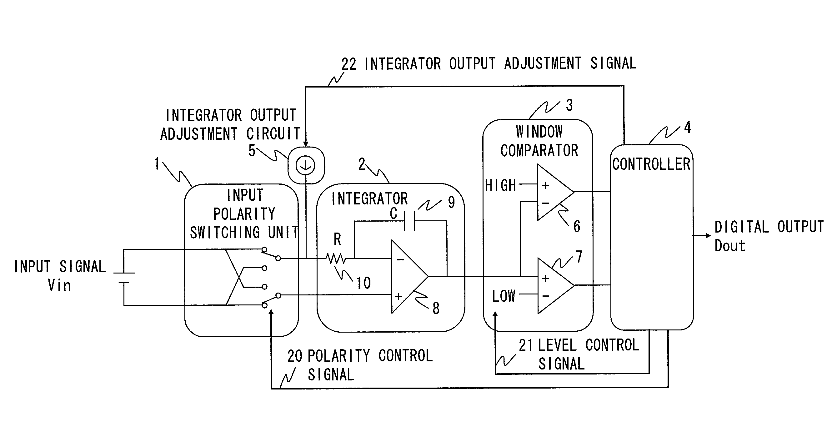
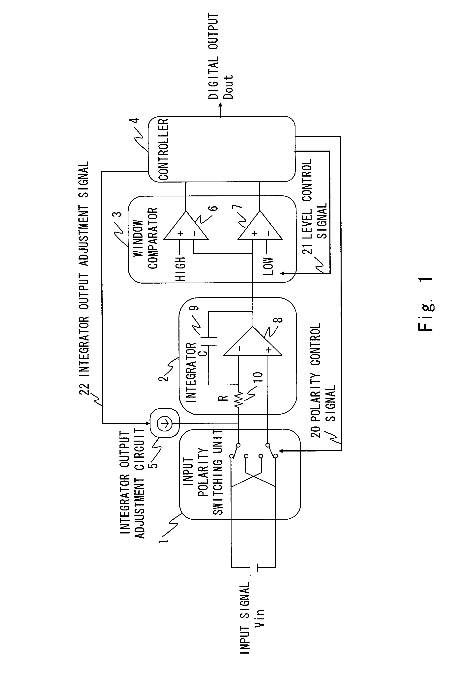
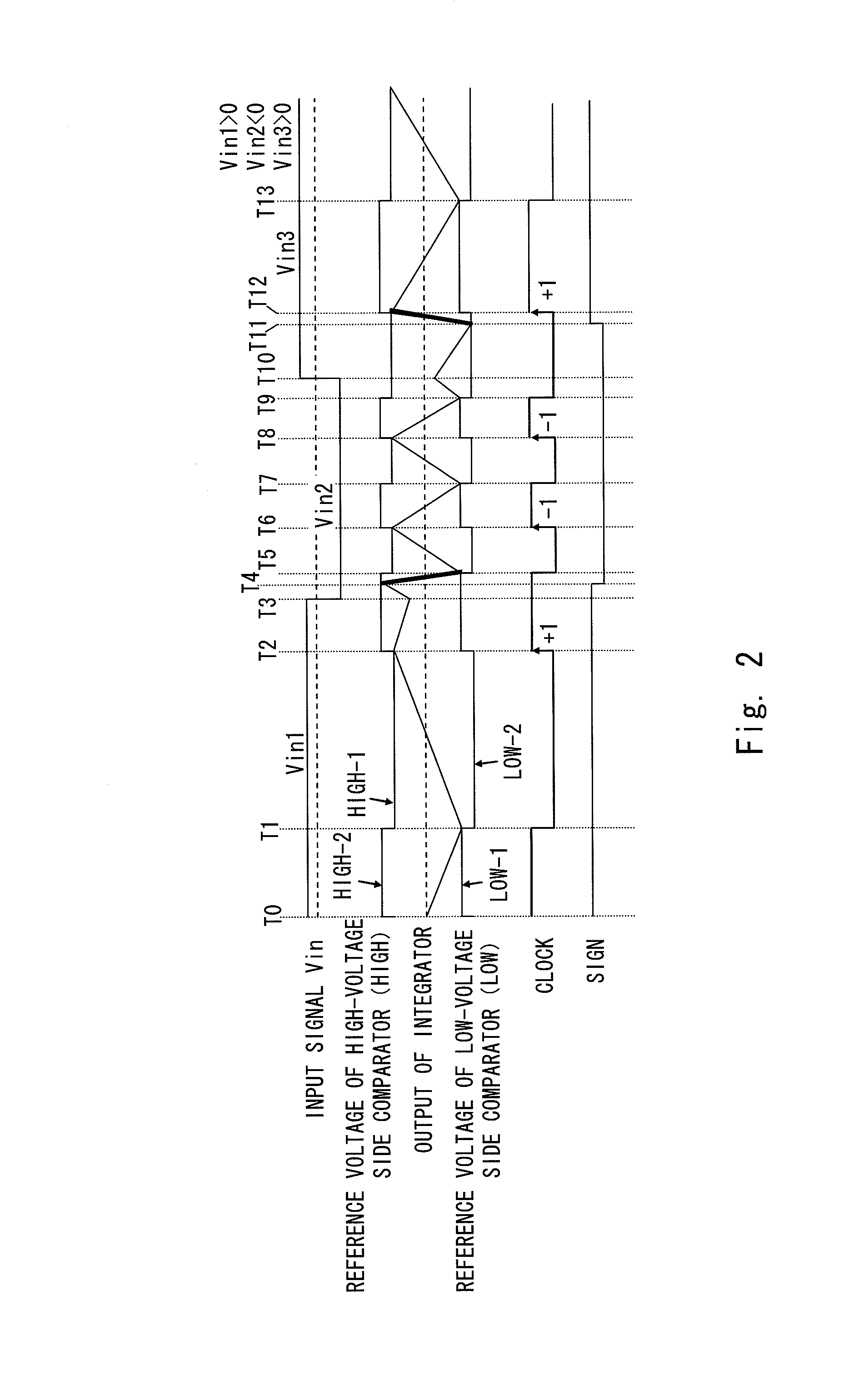
[0025]Hereinafter, the exemplary embodiment of the present invention will be described with reference to the drawings. FIG. 1 shows an analog-digital converter according to the exemplary embodiment of the present invention. In FIG. 1, the analog-digital converter includes an input polarity switching unit 1 that switches the polarity of an input signal, an integrator 2 that integrates the input signal output from the input polarity switching unit 1, and an integrator output adjusting circuit 5 that adjusts the output voltage of the integrator 2.

[0026]The analog-digital converter further includes a high-voltage side comparator 6 that includes a first reference voltage and a second reference voltage that is higher than the first reference voltage, a low-voltage side comparator 7 that includes a third reference voltage and a fourth reference voltage that is lower than the third reference voltage, and a window comparator that compares the output voltage of the integrator 2 with the first...


PUM


Abstract

An analog-digital converter according to the present invention includes an input polarity switching unit, an integrator that integrates an input signal, an integrator output adjusting circuit that adjusts an output voltage of the integrator, a window comparator, and a controller that controls the input polarity switching unit, the integrator output adjusting circuit, and the window comparator, and generates a digital signal. When the output voltage of the integrator reaches a first reference voltage, the controller resets reference voltage of a high-voltage side comparator to a second reference voltage. Further, when the output voltage of the integrator reaches a third reference voltage, the controller resets reference voltage of a low-voltage side comparator to a fourth reference voltage. According to the analog-digital converter of the present invention, it is possible to prevent device breakdown and occurrence of through current due to fluctuation of the output voltage of the integrator.

Description

INCORPORATION BY REFERENCE[0001]This application is based upon and claims the benefit of priority from Japanese patent application No. 2009-040551, filed on Feb. 24, 2009, the disclosure of which is incorporated herein in its entirety by reference.BACKGROUND[0002]1. Field of the Invention[0003]The present invention relates to an analog-digital converter that converts an analog signal to a digital signal.[0004]2. Description of Related Art[0005]In recent years, an analog-digital converter (ADC) that converts an analog signal to a digital signal has been used in various fields. FIG. 3 shows V-F (Voltage to Frequency) type of ADC disclosed in Japanese Unexamined Patent Application Publication No. 2007-139700.[0006]As shown in FIG. 3, a voltage-pulse converter 100 includes an input switching circuit 104, an integrator output inductive unit 105 as a voltage inductive unit, an integrator 108, first and second comparators 112 and 113 (window comparator), an RS latch circuit 114, first and ...

Claims


Application Information

Patent Timeline
Patent Type & Authority Applications(United States)
IPC IPC(8): H03M1/34
CPCH03K7/06H03M1/60H03M1/06
Inventor KOYAMA, TETSUHIRO
Owner RENESAS ELECTRONICS CORP
Why Eureka
Try Eureka