Level Sensor System

Inactive Publication Date: 2010-08-26
MOUNT EVEREST TECH
View PDF8 Cites 31 Cited by
  • Summary
  • Abstract
  • Description
  • Claims
  • Application Information

AI Technical Summary

Benefits of technology

[0051]The GPS Receiver Module provides standard, raw NMEA0183 (National Marine Electronics Association) strings or specific user-requested data via the serial command interface, tracking of up to 12 satellites, and WAAS / EGNOS (Wide Area Augmentation System / European Geostationary Navigation Overlay Service) functionality for more accurate positioning results.

Problems solved by technology

Usually, at the level of this float switch, there are opportunities for this mechanical switch to fail.

Method used


Image

  • Level Sensor System
  • Level Sensor System
  • Level Sensor System

Examples


Embodiment Construction

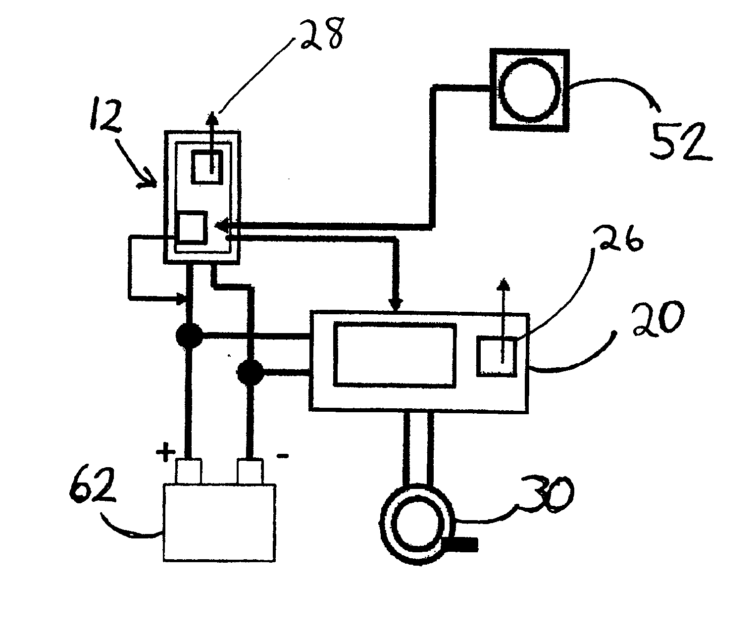
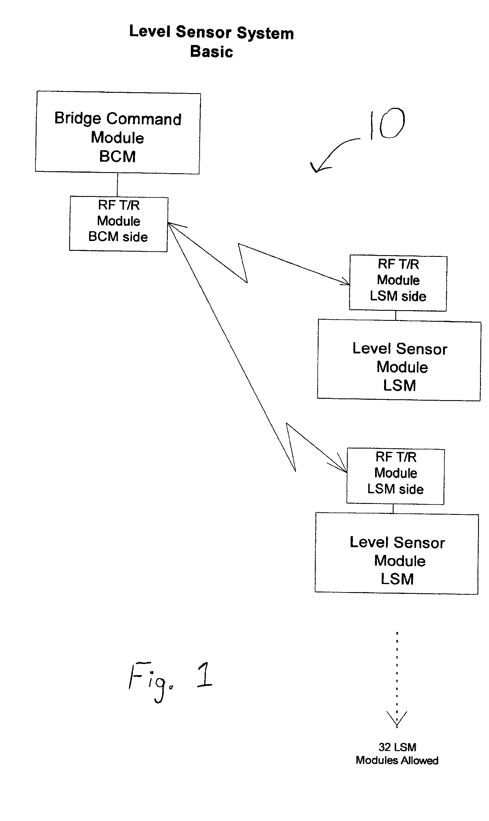
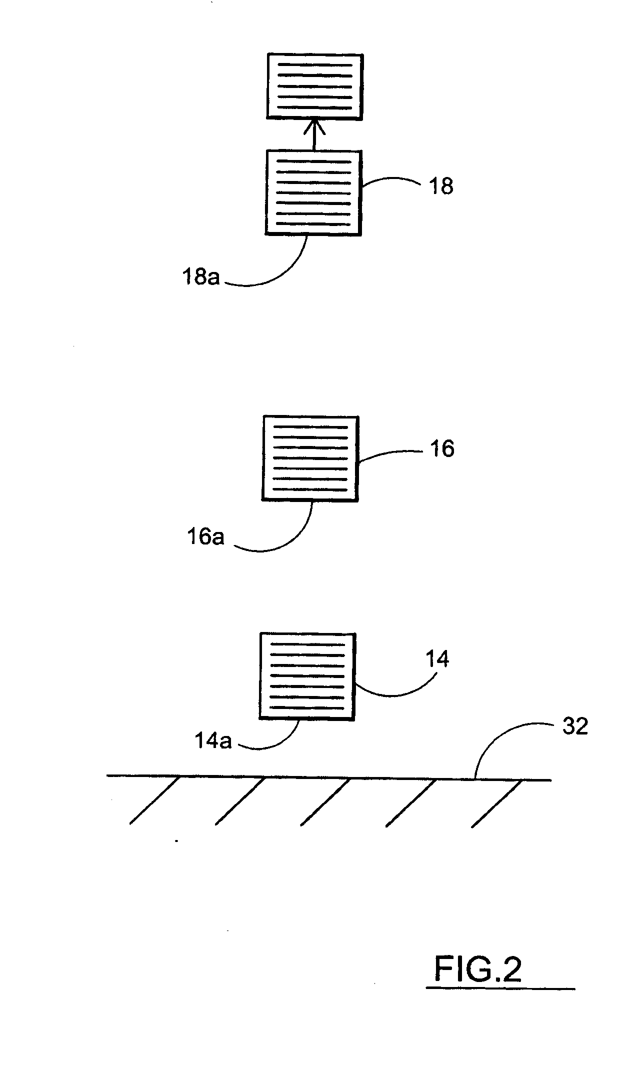
[0083]Referring now to FIGS. 1-6 and 11, System 10 includes a level sensor module (LSM) 12 which has contained therein a first, low sensor 14, and a second, high sensor 16. Optionally, level sensor module 12 can have a fewer number or greater number of sensors, for example, in one particular embodiment, shown in FIGS. 2-5, the LSM 12 includes a third, high high sensor 18. Each of low sensor 14 and high sensor 16 are positioned vertically above the bilge compartment section floor 32 of a waterborne vessel.

[0084]In one embodiment, the lower edge 14a of low sensor 14 is about 0.750 inches above bilge compartment floor 32. The lower edge 16a of high sensor 16 is about 4.25 inches above bilge compartment floor 32. In an embodiment using a high high sensor 18, lower edge 18a of high high sensor 18 is about 7.25 inches above bilge compartment floor 32. Level sensor module 12 has associated therewith, LSM microprocessor module 20.

[0085]Microprocessor module 20 controls: LSM 12; actuating me...


PUM


Abstract

A system and method for turning on and off a bilge pump whereby bilge water level is detected using level sensors and bilge pumps are turned on and off based on the detected water level. The system further incorporates an automatic transmission outside the watercraft to alert of the water level in the bilge. The system is controllable from within the watercraft and remotely controllable through wireless transmission.

Description

CROSS-REFERENCE TO RELATED APPLICATIONS[0001]This application claims priority to U.S. Provisional Application No. 61 / 155,566 filed on Feb. 26, 2009, the disclosure of which is incorporated herein by reference in its entirety.BACKGROUND OF THE INVENTION[0002]A bilge pump is a pump designed to remove bilge water. Because fuel can end up in the bilge compartment, electric bilge pumps are designed not to cause sparks. Electric bilge pumps are often fitted with float switches that turn on the pump when the bilge compartment fills to a set level. Usually, at the level of this float switch, there are opportunities for this mechanical switch to fail.[0003]The present invention addresses a need by providing a system and method for automating the cycle of turning on and off electronic bilge pumps or similar devices.BRIEF SUMMARY OF THE INVENTION[0004]The Level Sensor System (LSS) printed circuit board (PCB) provides the real-time control of a device, i.e. a pump and works as a stand-alone sys...

Claims


Application Information

Patent Timeline
IPC IPC(8): F04B49/06G01F23/00G08B21/00
CPCB63J4/00F04B49/02G01F23/0069F04B49/106F04D15/0218F04B49/022G01F23/802
Inventor ELLER, THEODOREHART, CHARLESPFARR, WILLIAMSPRAKER, JIM
Owner MOUNT EVEREST TECH
Why Eureka
Try Eureka