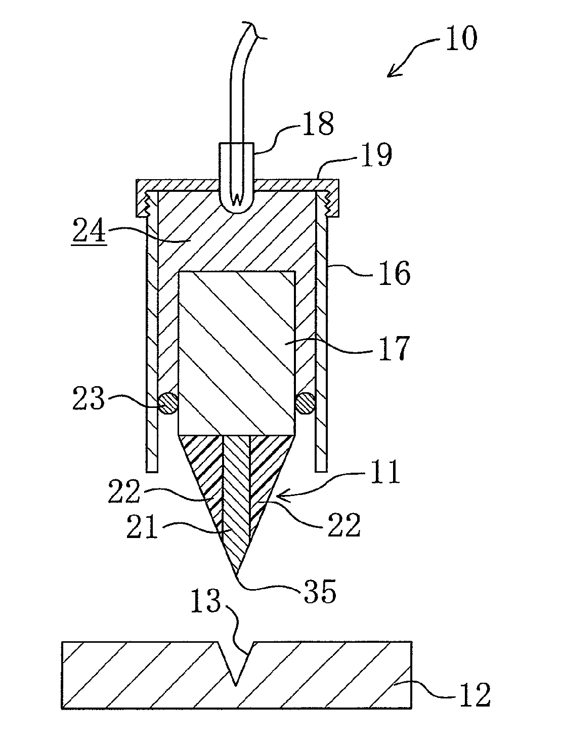
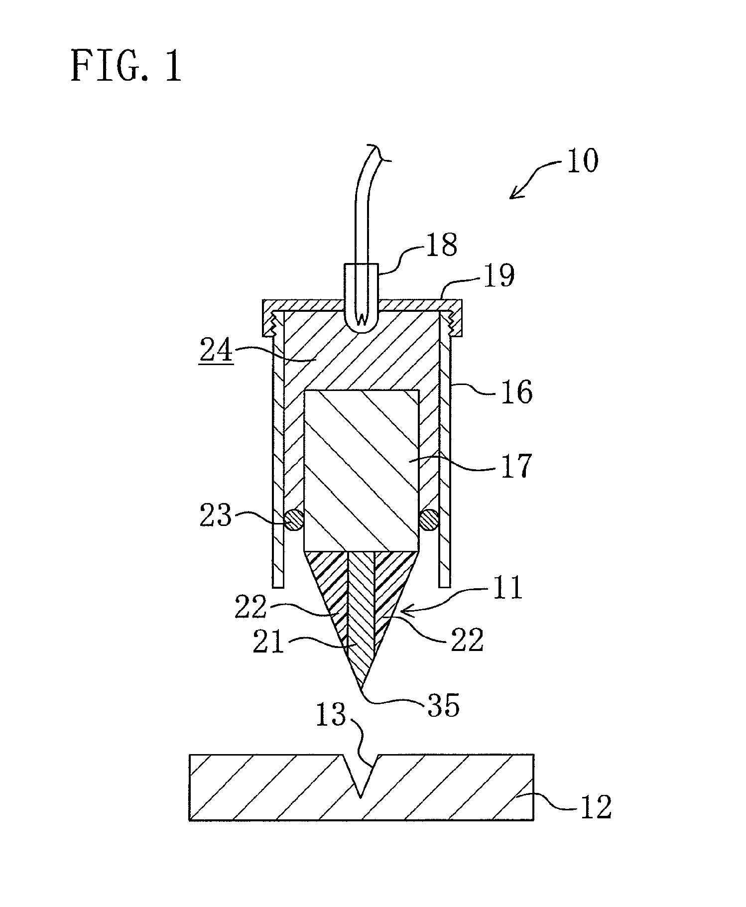
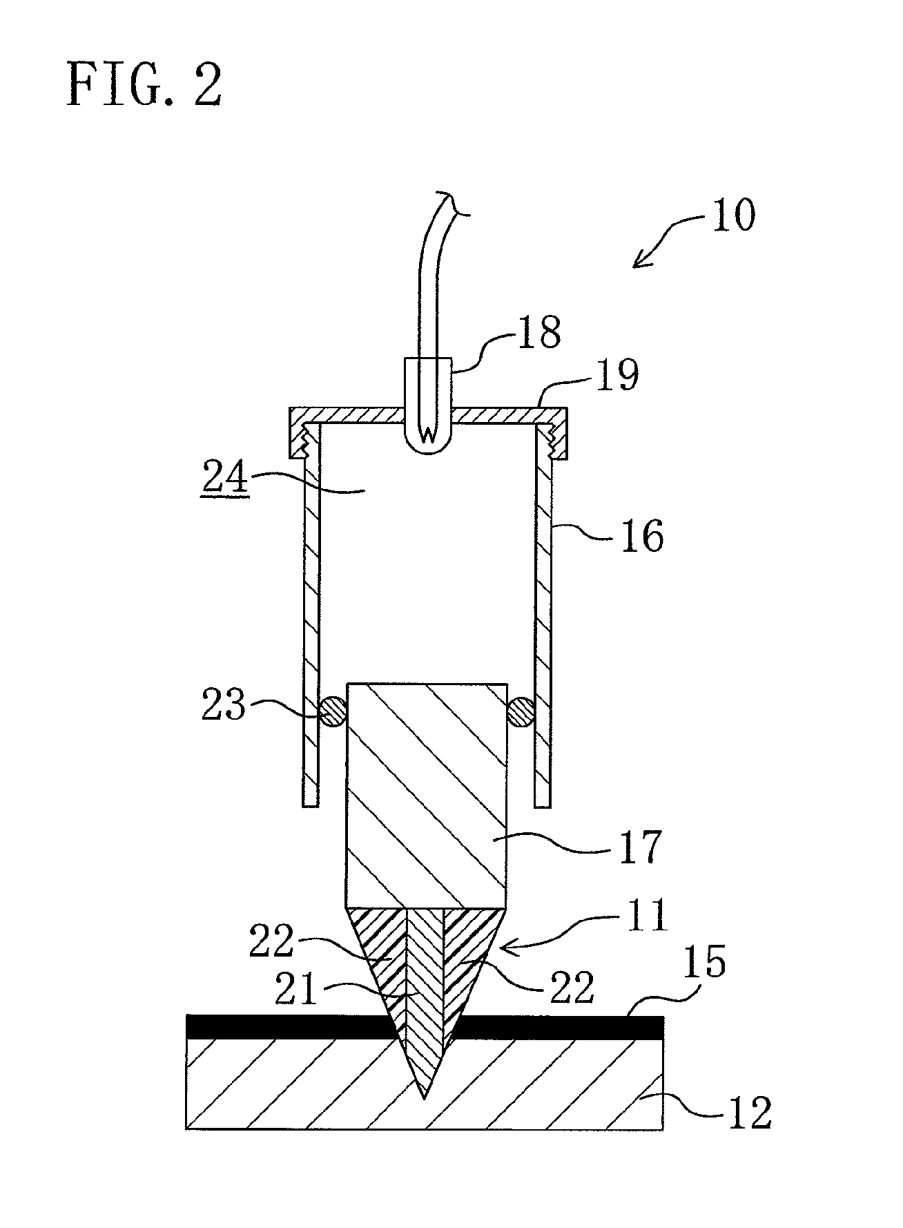
[0050]In the present invention, the insulating portion (22), which is subjected to a smaller force than the cutting portion (21) and does not delaminate like a
coating film, eventually contacts the cut faces of the current-carrying member (15). Thus, the cutting portion (21), which is made of a
metal, does not contact the cut faces of the current-carrying member (15) after the blade (11) advances, whereby electricity can be reliably prevented from flowing between the cut pieces of the current-carrying member (15).
[0051]In the third invention, the placing hole (26), which is configured to place therein the current-carrying member (15) to be cut, is formed in the cylindrical case (16) configured to accommodate the blade (11). Thus, the current-carrying member (15) to be cut can be easily placed at a predetermined position by merely inserting the current-carrying member (15) through the placing hole (26).
[0052]In the fourth to eighth inventions, the cut pieces of the current-carrying member (15) are prevented from contacting the case main body (41) that is made of a metal. This can prevent electricity from flowing between the cut pieces of the current-carrying member (15) via the case main body (41).
[0053]In the fifth invention, the case insulating portion (42) serves not only to prevent the cut pieces of the current-carrying member (15) from contacting a region surrounding the placing hole (26), but also to fix the current-carrying member (15). This eliminates the need to separately provide a member configured to fix the current-carrying member (15), whereby the configuration of the cutting apparatus (10) can be simplified.
[0054]In the sixth invention, the outer
peripheral surface of the cutting portion (21) faces also the inner
peripheral surface of the fixing member (42b) located on the side to which the blade (11) advances, before the blade (11) advances. Thus, even if there is a placement error of the pair of fixing members (42a, 42b), the cutting portion (21) does not hit this fixing member (42b) during advancing movement. This enables the blade (11) to reliably advance to a predetermined advanced position where the insulating portion (22) insulates the cut pieces of the insulating member (15) from each other, regardless of the placement error of the pair of fixing members (42a, 42b).
[0055]In the ninth invention, the gas generated in the gas generating portion (24) is prevented from reaching the vicinity of the cut faces of the current-carrying member (15) through the gap between the inner surface of the cylindrical case (16) and the outer surface of the insulating portion (22). The gas generated in the gas generating chamber (24) may have been plasmatized. If such a gas reaches the vicinity of the cut faces of the current-carrying member (15), electricity can flow between the current-carrying member (15) and the cylindrical case (16) via the gas. Moreover, a conductive product may be produced in the gas generating chamber (24) by a reaction of the gas generating agent. If such a conductive product reaches the vicinity of the cut faces of the current-carrying member (15) together with the gas generated in the gas generating chamber (24), electricity can flow between the current-carrying member (15) and the cylindrical case (16) via the conductive product. On the other hand, in the ninth invention, the gas generated in the gas generating chamber (24) is prevented from reaching the vicinity of the cut faces of the current-carrying member (15). Thus, electricity can be prevented from flowing between the current-carrying member (15) and the cylindrical case (16) via the gas generated in the gas generating chamber (24) and / or the conductive product produced in the gas generating chamber (24).
[0056]In the eleventh invention, the latching protruding portion (45) fits in the placing hole (26) after the blade (11) advances. Thus, even if the blade (11) rebounds after advancing, the latching protruding portion (45) is caught by the
peripheral side surface of the placing hole (26). This prevents the blade (11) from rebounding greatly. If the blade (11) rebounds greatly, the cutting portion (21) can return to the position between the cut pieces of the current-carrying member (15), causing electricity to flow between the cut pieces of the current-carrying member (15) via the cutting portion (21). In the eleventh invention, since the blade (11) does not rebound greatly, electricity can be prevented from flowing between the cut pieces of the current-carrying member (15) via the cutting portion (21).
[0021]According to a thirteenth invention, in any one of the first to twelfth inventions, the cutting apparatus (10) further includes a blade stop portion (32) positioned on a side to which the blade (11) advances, so that the cutting portion (21) fits in the blade stop portion (32) after cutting the current-carrying member (15).
[0058]In the thirteenth invention, the cutting portion (21) fits in the blade stop portion (32) after cutting the current-carrying member (15). Thus, the blade (11) hardly rebounds after hitting the blade stop portion (32). This can prevent electricity from flowing between the cut pieces of the current-carrying member (15) via the cutting portion (21).
[0059]In the sixteenth invention, the fitting groove (33) extends in a circular shape corresponding to the shape of the cutting edge of the blade portion of the cutting portion (21). Thus, the cutting edge of the blade portion of the cutting portion (21) fits in the fitting groove (33) even if the cutting portion (21) rotates. In the case where both the cutting edge of the cutting portion (21) and the fitting groove (33) extend linearly, the respective extending directions of the cutting edge of the cutting portion (21) and the fitting groove (33) need to be matched with each other. This requires adjustment in the rotation direction when attaching the cutting portion (21) and the blade stop portion (32), thereby complicating the attaching operation. On the other hand, in the sixteenth invention, the cutting edge of the blade portion of the cutting portion (21) fits in the cutting groove (33) even if the cutting portion (21) rotates. Thus, no such adjustment in the rotation direction is required when attaching the cutting portion (21) and the blade stop portion (32), thereby facilitating the operation of attaching the cutting portion (21) and the blade stop portion (32).
[0062]In the twentieth invention, the cutting apparatus (10) is capable of forcibly interrupting the current flow between the power supply terminal (94) and the load terminal (95). Conventionally, if, e.g., the movable contact (53) and the fixed contact (52) are welded together in the breaker (50), or the movable contact (73) and the fixed contact (68, 69) are welded together in the
contactor (70), the current flow between the power supply terminal (94) and the load terminal (95) may not be interrupted even in the event of an abnormal current. This can cause failures of load equipments. On the other hand, in the twentieth invention, the cutting apparatus (10) is capable of forcibly interrupting the current flow between the power supply terminal (94) and the load terminal (95) even if, e.g., the breaker (50) and the
contactor (70) are welded together. This can reliably prevent failures of the load equipments in the event of an abnormal current.
[0062]In the twentieth invention, the cutting apparatus (10) is capable of forcibly interrupting the current flow between the power supply terminal (94) and the load terminal (95). Conventionally, if, e.g., the movable contact (53) and the fixed contact (52) are welded together in the breaker (50), or the movable contact (73) and the fixed contact (68, 69) are welded together in the
contactor (70), the current flow between the power supply terminal (94) and the load terminal (95) may not be interrupted even in the event of an abnormal current. This can cause failures of load equipments. On the other hand, in the twentieth invention, the cutting apparatus (10) is capable of forcibly interrupting the current flow between the power supply terminal (94) and the load terminal (95) even if, e.g., the breaker (50) and the contactor (70) are welded together. This can reliably prevent failures of the load equipments in the event of an abnormal current.

