Thermoelectric conversion module

a technology of conversion module and thermoelectric element, which is applied in the direction of thermoelectric device junction materials, electrical apparatus, thermoelectric device with peltier/seeback effect, etc., can solve the problems that conventional methods cannot sufficiently inhibit the fracture of the substrate or of the thermoelectric conversion element, and achieve the effect of small thermal expansion coefficient, small thermal expansion coefficient and large thermal expansion coefficien

Inactive Publication Date: 2010-09-02
SUMITOMO CHEM CO LTD
View PDF9 Cites 20 Cited by
  • Summary
  • Abstract
  • Description
  • Claims
  • Application Information

AI Technical Summary

Benefits of technology

[0016]When the thermal expansion coefficient of the electrode is larger than the thermal expansion coefficients of the p-type thermoelectric conversion elements and the n-type thermoelectric conversion elements, the following effects can be shown by setting the height of the thermoelectric conversion elements having a larger thermal expansion coefficient so as to be higher than that of the thermoelectric conversion elements having a smaller thermal expansion coefficient.
[0017]In the thermoelectric conversion elements having the smaller thermal expansion coefficient, the height of any one of them is lower than the height of any one of the thermoelectric conversion elements having a larger thermal expansion coefficient, and the electrodes bonded with the upper and lower faces of this thermoelectric conversion element through the bonding members can take over the height corresponding to the difference. In other words, the total thickness of parts of a pair of electrodes connected to any one of the thermoelectric conversion elements having a smaller thermal expansion coefficient, the parts facing the thermoelectric conversion element to which the electrodes are connected, can be set so as to be larger than the total thickness of parts of a pair of electrodes connected to any one of the thermoelectric conversion elements having a larger thermal expansion coefficient, the parts facing the thermoelectric conversion element to which the electrodes are connected. Accordingly, the expansion amount of the electrode having a larger thermal expansion coefficient than any thermoelectric conversion element can be increased and the total expansion amount of the thermoelectric conversion element and the pair of the electrodes can be increased, in the side of the thermoelectric conversion element having a smaller thermal expansion coefficient. Therefore, a difference between the total thermal expansion amount of the thermoelectric conversion element and the pair of the electrodes in the side of the thermoelectric conversion element having a smaller thermal expansion coefficient and the total expansion amount of the thermoelectric conversion element and the pair of the electrodes in the side of the thermoelectric conversion element having a larger thermal expansion coefficient can be reduced, in comparison with those in the case in which the heights of the n-type and the p-type thermoelectric conversion elements are equal.
[0018]On the contrary, when the thermal expansion coefficient of the electrode is smaller than the thermal expansion coefficients of the p-type thermoelectric conversion elements and the n-type thermoelectric conversion elements, the following effects can be shown by setting the height of the thermoelectric conversion elements having a larger thermal expansion coefficient so as to be lower than that of the thermoelectric conversion elements having a smaller thermal expansion coefficient.
[0019]In the thermoelectric conversion elements having the larger thermal expansion coefficient, the height of any one of them is lower than the height of any one of the thermoelectric conversion elements having a smaller thermal expansion coefficient, and the electrodes bonded with the upper and lower faces of any one of the thermoelectric conversion elements through the bonding members can take over the height corresponding to the difference. In other words, the total thickness of parts of a pair of electrodes connected to any one of the thermoelectric conversion elements having a larger thermal expansion coefficient, the parts facing the thermoelectric conversion element to which the electrodes are connected, can be set so as to be larger than the total thickness of parts of a pair of electrodes connected to any one of the thermoelectric conversion elements having a smaller thermal expansion coefficient, the parts facing the thermoelectric conversion element to which the electrodes are connected. Accordingly, the ratio of the electrode having a smaller thermal expansion coefficient than any thermoelectric conversion element increases, and the total thermal expansion amount of the thermoelectric conversion element and the pair of the electrodes can be reduced, in the side of the thermoelectric conversion element having a larger thermal expansion coefficient. Therefore, a difference between the total thermal expansion amount of the thermoelectric conversion element and the pair of the electrodes in the side of the thermoelectric conversion element having the smaller thermal expansion coefficient and the total expansion amount of the thermoelectric conversion element and the pair of the electrodes in the side of the thermoelectric conversion element having the larger thermal expansion coefficient can be reduced.

Problems solved by technology

However, conventional methods could not sufficiently inhibit the fracture of the substrate or of the thermoelectric conversion element and the bonding failure between the thermoelectric conversion element and the electrode from occurring when having been used in the high-temperature environment.

Method used


Image

  • Thermoelectric conversion module
  • Thermoelectric conversion module
  • Thermoelectric conversion module

Examples


first embodiment

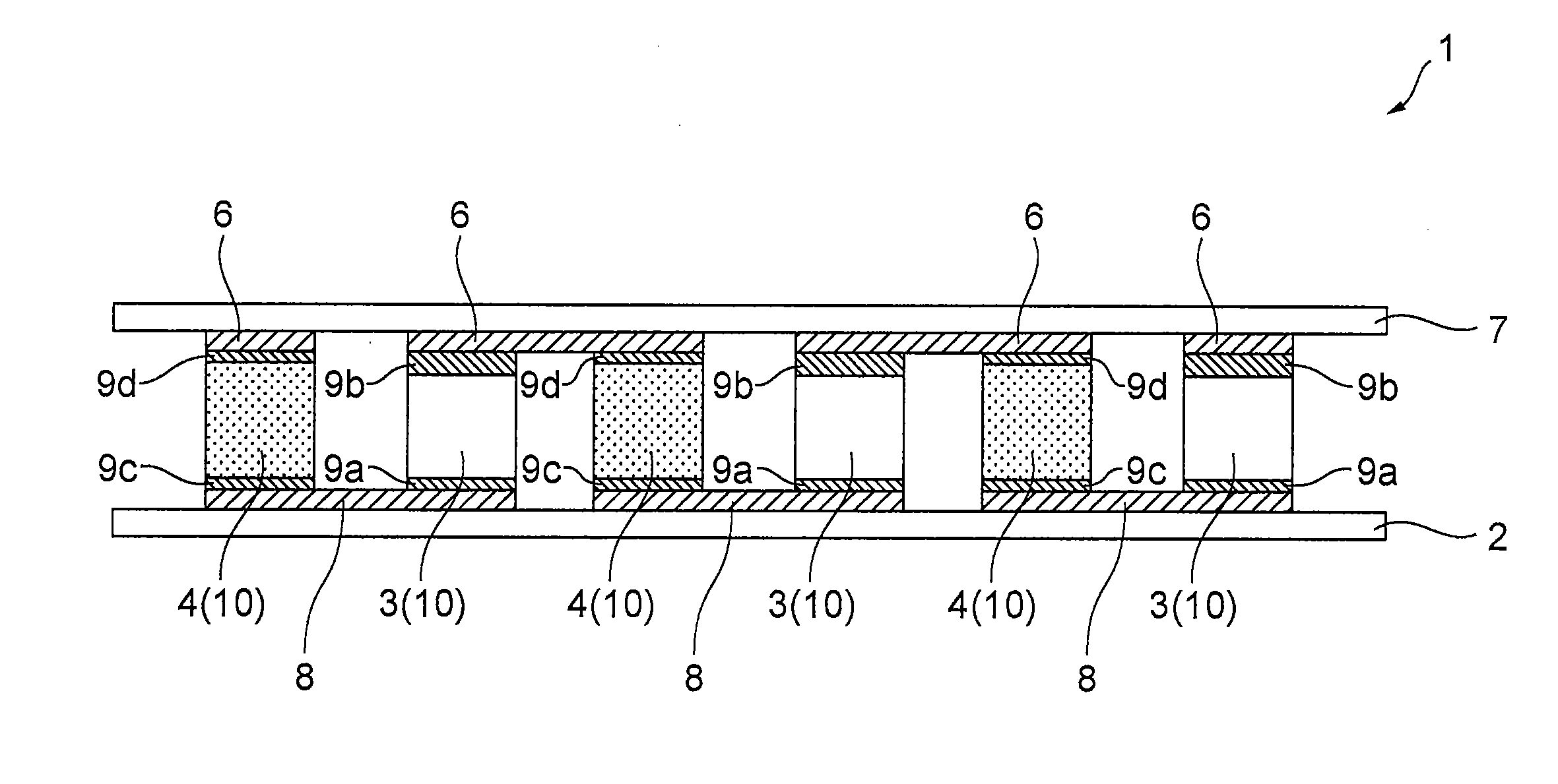
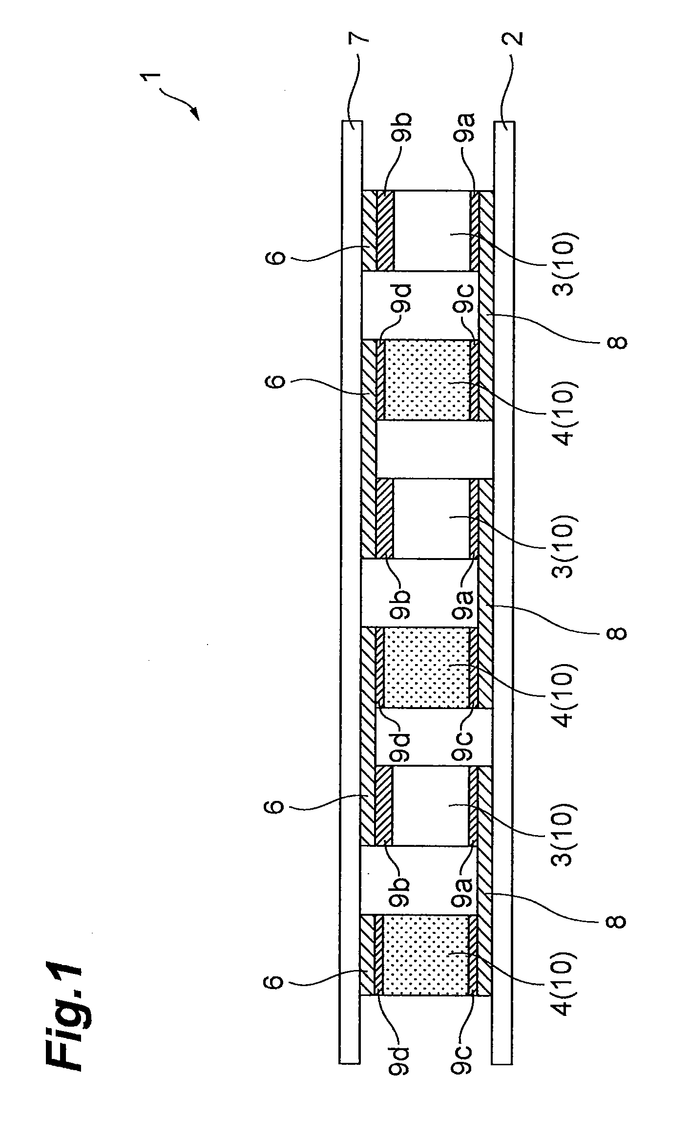
[0027]FIG. 1 illustrates a sectional view of a thermoelectric conversion module 1 in a first embodiment. As is illustrated in FIG. 1, the thermoelectric conversion module 1 comprises a first substrate 2, a first electrode 8, a thermoelectric conversion element 10, a second electrode 6 and a second substrate 7.

[0028]The first substrate 2 has, for instance, a rectangular shape, has electrically insulating properties and thermal conductance, and covers one ends of a plurality of the thermoelectric conversion elements 10. Examples of the materials for this first substrate include alumina, aluminum nitride and magnesia.

[0029]The first electrode 8 is provided on the first substrate 2, and electrically connects one end faces of mutually adjacent thermoelectric conversion elements 10 with each other. This first electrode 8 can be formed at a predetermined position on the first substrate 2, for instance, with a thin film method such as sputtering and vapor deposition, and with a method such ...

second embodiment

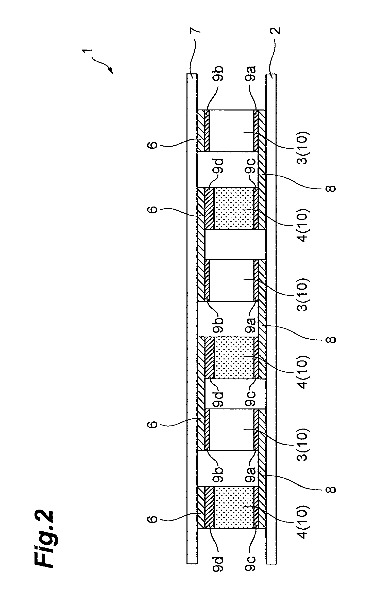
[0050]FIG. 2 illustrates a sectional view of a thermoelectric conversion module 1 in a second embodiment.

[0051]The first point at which the thermoelectric conversion module 1 according to the second embodiment is different from the thermoelectric conversion module 1 according to the first embodiment is a point that thermal expansion coefficient of the bonding members 9a to 9d is smaller than thermal expansion coefficients of the p-type thermoelectric conversion element 3 and the n-type thermoelectric conversion element 4. The second point is a point that the height of the n-type thermoelectric conversion element 4 having a larger thermal expansion coefficient of the p-type thermoelectric conversion element 3 and the n-type thermoelectric conversion element 4 is set so as to be lower than the height of the p-type thermoelectric conversion element 3 having a smaller thermal expansion coefficient.

[0052]Because the height of the n-type thermoelectric conversion element 4 having a larger...

third embodiment

[0054]FIG. 3 illustrates a sectional view of a thermoelectric conversion module 1 in a third embodiment.

[0055]The points at which the thermoelectric conversion module 1 according to the third embodiment is different from the thermoelectric conversion module 1 according to the first embodiment is a point that the total thickness of the pair of the bonding members 9a, 9b in the side of the p-type thermoelectric conversion element 3 having a smaller thermal expansion coefficient is equal to the total thickness of the pair of the bonding members 9c, 9d in the side of the n-type thermoelectric conversion element 4 having a larger thermal expansion coefficient, and a point that the total thickness of parts 6a, 8a of a pair of electrodes 6, 8 connected to the n-type thermoelectric conversion element 4 having a larger thermal expansion coefficient, the parts 6a, 8a facing the thermoelectric conversion element 4 to which the electrodes 6, 8 are connected, is smaller than the total thickness ...


PUM


Abstract

Provided is a thermoelectric conversion module. This thermoelectric conversion module comprises a pair of substrates facing each other, a plurality of p-type thermoelectric conversion elements and a plurality of n-type thermoelectric conversion elements arranged between the paired substrates, a plurality of electrodes mounted individually on the paired substrates, connecting individual paired end faces of the p-type thermoelectric conversion elements and the n-type thermoelectric conversion elements electrically with each other, and connecting the p-type thermoelectric conversion elements and the n-type thermoelectric conversion elements electrically in series alternately, and a plurality of bonding members for bonding the p-type thermoelectric conversion elements and the n-type thermoelectric conversion elements individually with the electrodes. The thermal expansion coefficients of the p-type thermoelectric conversion elements and the n-type thermoelectric conversion elements are different from each other and the heights of the p-type thermoelectric conversion elements and the n-type thermoelectric conversion elements are different from each other.

Description

TECHNICAL FIELD[0001]The present invention relates to a thermoelectric conversion module.BACKGROUND ART[0002]A structure in which p-type and n-type thermoelectric conversion elements between one pair of substrates are bonded with electrodes through bonding members is known as a structure of a thermoelectric conversion module (Japanese Patent Application Laid-Open Publication No. 2006-332443, for instance). In such a thermoelectric conversion module, the p-type thermoelectric conversion element and the n-type thermoelectric conversion element have usually the same shape, as is disclosed in “Research-and-development report of thermoelectric conversion art using expressway bus exhaust gas” of a result report of fiscal 2002, p 11 (2003), by New Energy and Industrial Technology Development Organization.[0003]By the way, there is a case in which the thermoelectric conversion module is used in a high-temperature environment such as 400° C., for instance. In this case, there could be a prob...

Claims


Application Information

Patent Timeline
Patent Type & Authority Applications(United States)
IPC IPC(8): H01L35/16H01L35/00
CPCH01L35/32H01L35/22H10N10/855H10N10/17
Inventor HIROYAMA, YUICHI
Owner SUMITOMO CHEM CO LTD
Why Eureka
Try Eureka