
Electromagnetic induction type heating device, hot air generating device and electrical power generating device

Inactive Publication Date: 2010-09-02
MATSUI
View PDF4 Cites 12 Cited by
  • Summary
  • Abstract
  • Description
  • Claims
  • Application Information

AI Technical Summary

Benefits of technology

[0005]However, the conventional devices described above were used for fixing toner in copiers and for drying / heating industrial materials, and the fact of the matter is that these are substantially never used as heat sources for ordinary households or as heating devices in the field of agriculture. The present invention is a reflection of the problems in the prior art such as described above, and an object thereof is to provide an electromagnetic induction type heating device, a hot air generating device and a electrical power generating device with a simple structure, which is useful as a high-efficiency, safe and economical heat source for ordinary households and in the field of agriculture.

Problems solved by technology

However, the conventional devices described above were used for fixing toner in copiers and for drying / heating industrial materials, and the fact of the matter is that these are substantially never used as heat sources for ordinary households or as heating devices in the field of agriculture.

Method used


Image

  • Electromagnetic induction type heating device, hot air generating device and electrical power generating device
  • Electromagnetic induction type heating device, hot air generating device and electrical power generating device
  • Electromagnetic induction type heating device, hot air generating device and electrical power generating device

Examples


embodiment 1

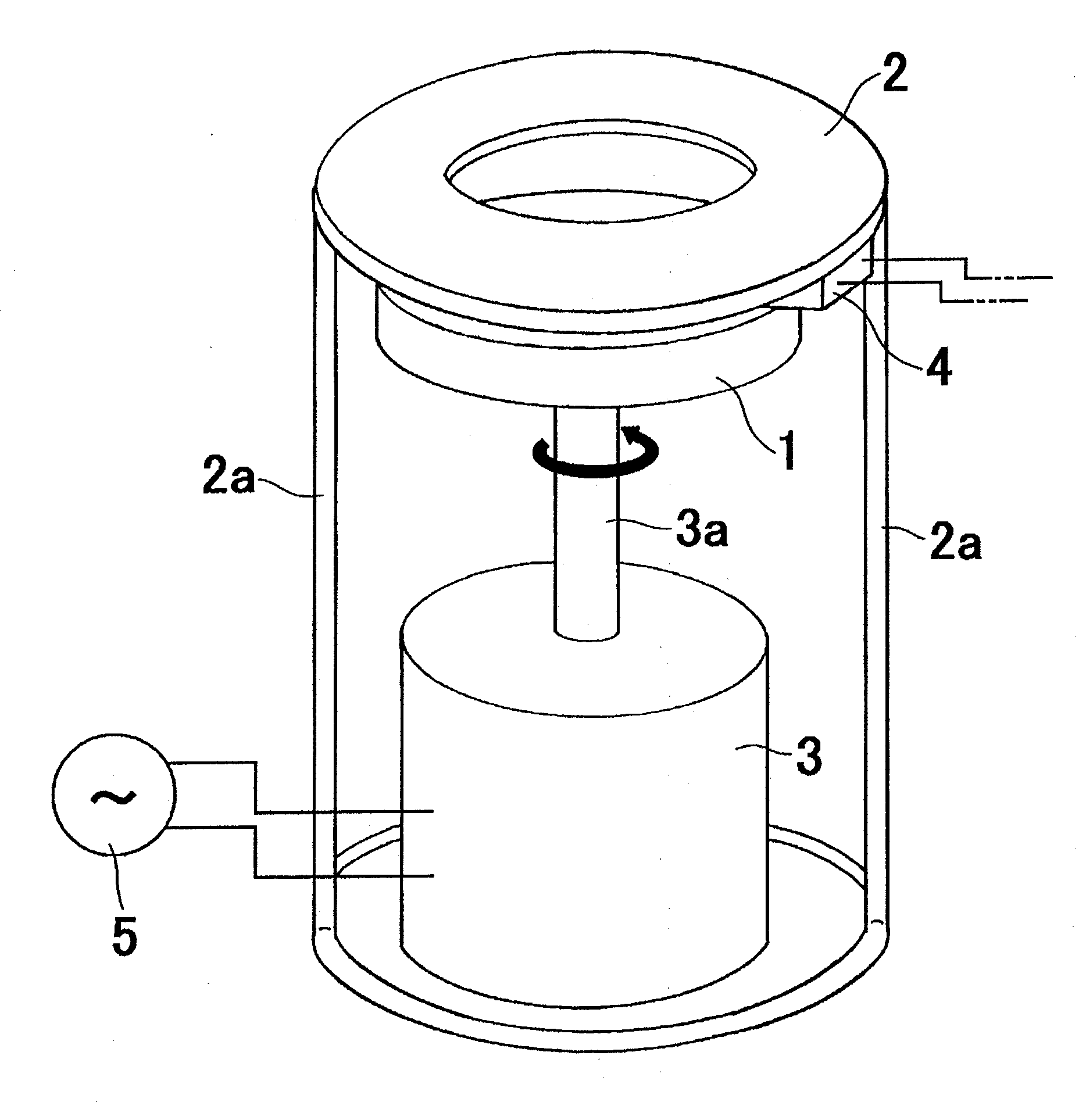
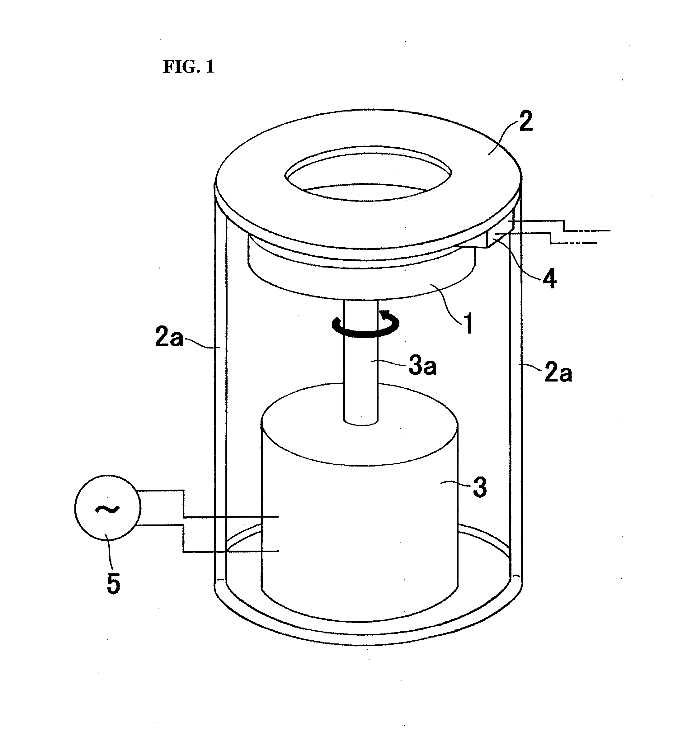
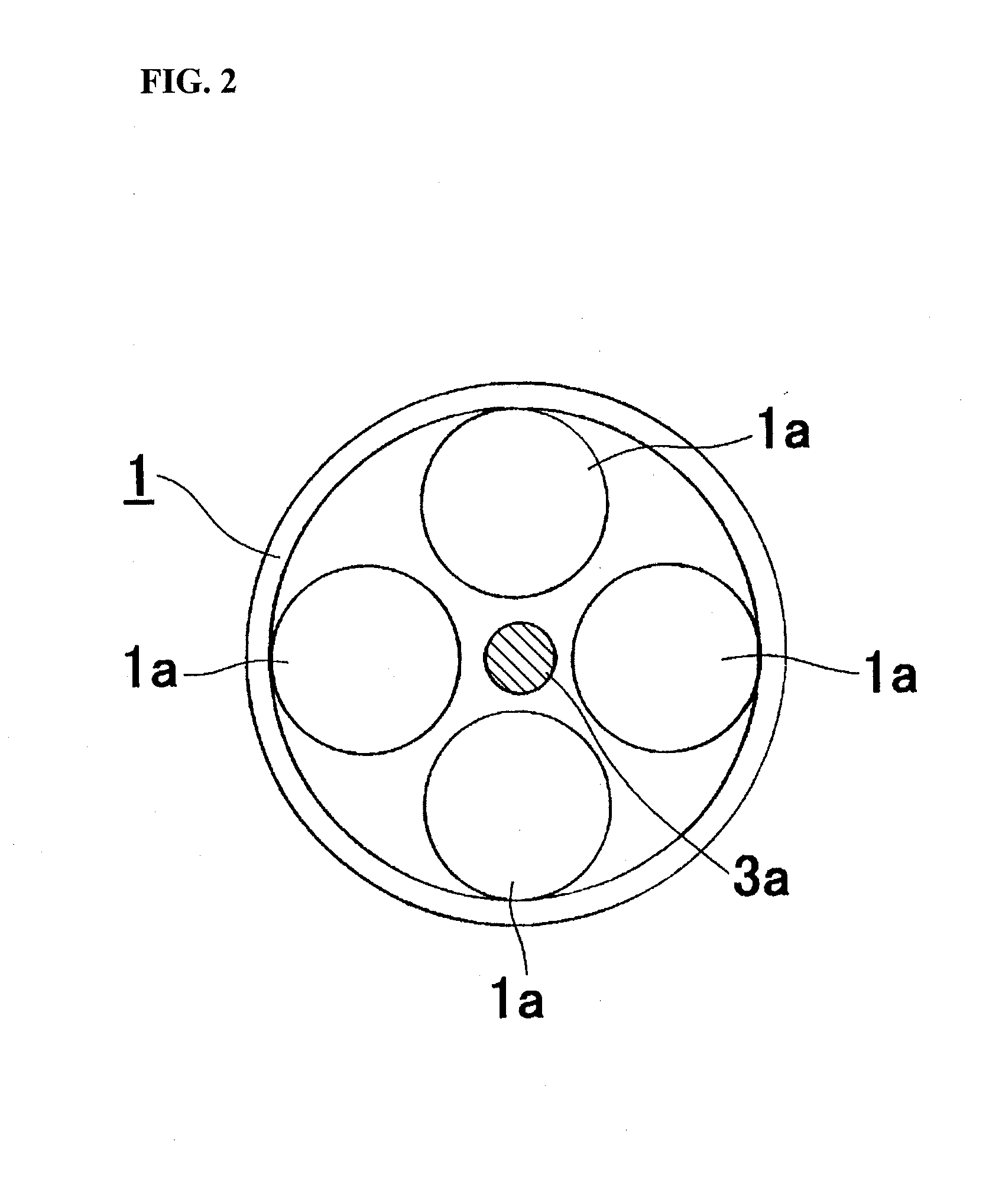
[0015]FIG. 1 is a perspective view showing one embodiment of an electromagnetic induction type heating device according to the present invention; and FIG. 2 is a view showing the arrangement of permanent magnets in the rotating body.

[0016]The heat generating device of the present invention is such that a heat generation part 2 embodied as an annular disk made from aluminum is disposed so as to be fixed in place upright by means of leg supports 2a, above and in the vicinity of (25 mm in the present embodiment) a planar rotating body 1, on which a plurality of permanent magnets 1a are fixed in place at arbitrary intervals.

[0017]The permanent magnets 1a are arranged in a circle on the rotating body 1 at uniform intervals. The permanent magnets 1a may be arranged so that north poles and south poles are alternatingly positioned, or may be arranged so that like poles are adjacent to each other. The number thereof disposed is likewise arbitrary. The rotating body 1 is rotated at high speed...

embodiment 2

[0019]FIG. 3 is a perspective view showing one embodiment of an electromagnetic induction type hot air generating device according to the present invention; and FIG. 4(a) is a sectional plan view, while FIG. 4(b) is a sectional front view of a hot air capture part.

[0020]As shown in FIG. 3, the electromagnetic induction type hot air generating device of the present invention is such that a disk, which is made of aluminum, and serves as the heat generation part 2, is fixed in place in an upright manner above, and in the vicinity of, a planar rotating body 1, on which a plurality of permanent magnets 1a as shown in FIG. 2 are fixed in place at arbitrary intervals; and an hot air capture part 10, having substantially the same diameter, is disposed and fixed in place in an upright manner above, and in the vicinity of, this disk, by way of the support legs 2a.

[0021]Flanges 6b are integrally formed with the heat generation part 2 and a hot air capture plate 6 of the hot air capture part 1...


PUM

PropertyMeasurementUnit
Poweraaaaaaaaaa
Magnetic fieldaaaaaaaaaa

Abstract

Permanent magnets are arranged at the interior of a rotating body at uniform intervals. The device comprises: a rotating body which is rotated by a motor; a heat generation part, which is disposed in the vicinity of the rotating body, which includes an electroconductive material, and which is disposed within the magnetic fields of the permanent magnets; and a hot air capture plate, which is disposed in the vicinity of the heat generation part, and in which a plurality of hot air flow passage holes are provided, the rotating body being rotated by a rotating shaft, which is coupled to the motor. Furthermore, a thermocouple may be connected to the heat generation part, and the heat energy that would be dissipated to the outside air is converted to electrical energy by the thermocouple. Furthermore, the electromagnetic induction device is constituted such that a hot air capture plate, in which a plurality of hot air flow passage holes are provided, is disposed in the vicinity of the heat generation part.

Description

BACKGROUND OF THE INVENTION[0001]The present invention relates to electromagnetic induction type heating devices, hot air generating devices and an electrical power generating devices, wherein hot air is generated as a result of Joule heating produced by generating an eddy current, using permanent magnets; more particularly it relates to electromagnetic induction type heating devices, hot air generating devices and electrical power generating devices, suitably employed as hot air generating devices, which use the hot air generated for heating greenhouses, for residential heating and for melting accumulated snow, and as power source devices, wherein some of the heat that is generated is reconverted to electrical power.[0002]Conventionally, various different electromagnetic induction type heating devices have been proposed, which use induction heating methods in which an AC magnetic field is generated by an AC current. For example, in terms of induction heating devices comprising an e...

Claims


Application Information

Patent Timeline
IPC IPC(8): H05B6/02F24D18/00
CPCF24H3/0405H05B6/109H05B6/108F24H2240/08F24D18/00F24D2101/60
Inventor MATSUI
Owner MATSUI
Learn More