Photoelectric conversion apparatus

Inactive Publication Date: 2010-09-02
CANON KK
View PDF9 Cites 0 Cited by
  • Summary
  • Abstract
  • Description
  • Claims
  • Application Information

AI Technical Summary

Benefits of technology

[0007]The present invention has been made in view of the above-mentioned circumstances, and an object of the present invention is to provide a ph

Problems solved by technology

While the abovementioned area-type phase difference detection AF sensor is used for high-speed and high-precision auto-

Method used


Image

  • Photoelectric conversion apparatus
  • Photoelectric conversion apparatus
  • Photoelectric conversion apparatus

Examples


Example

First Embodiment

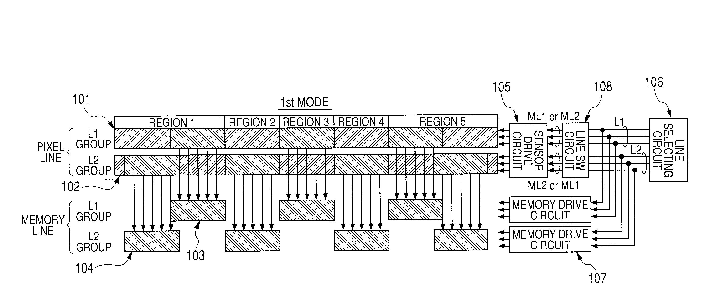
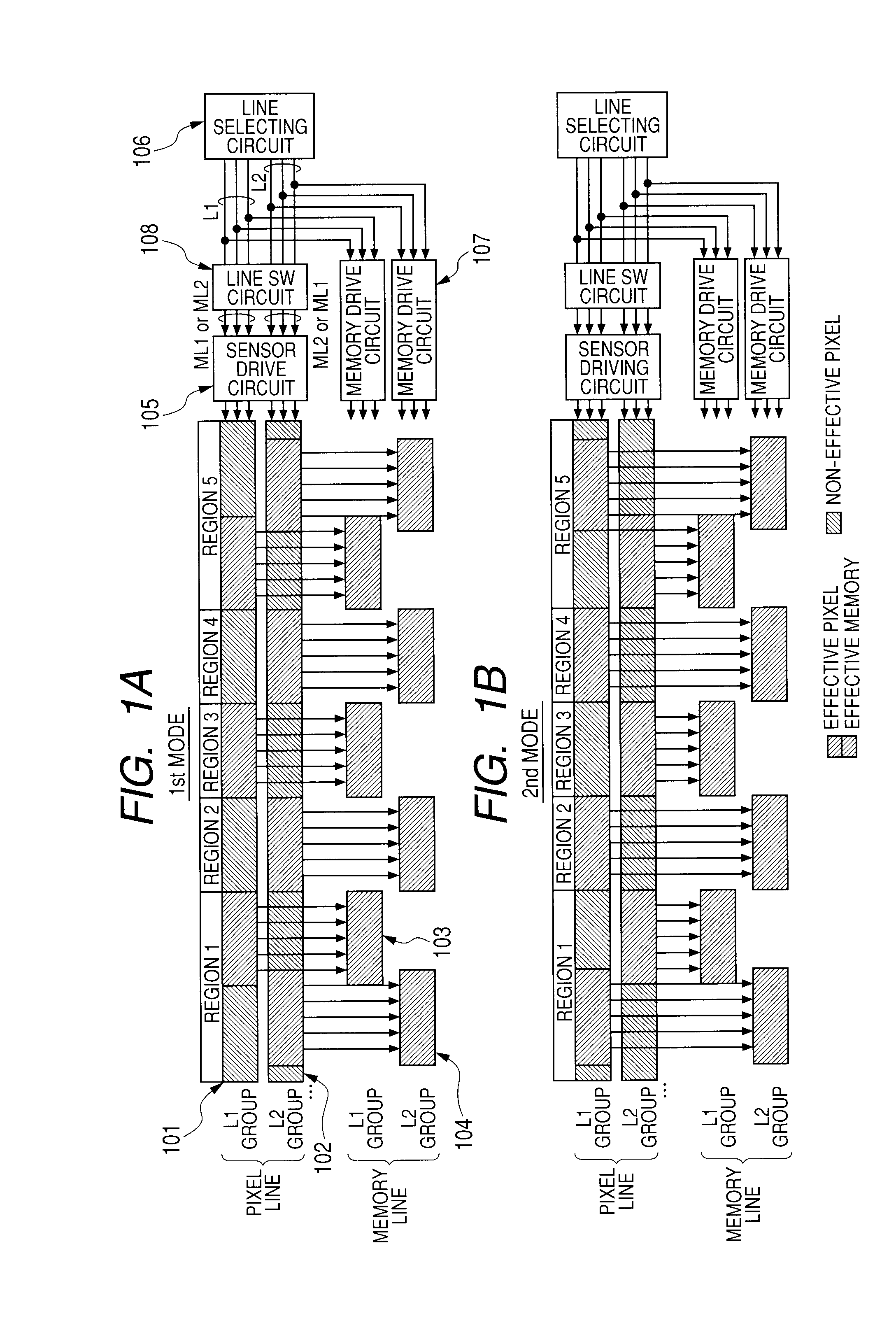
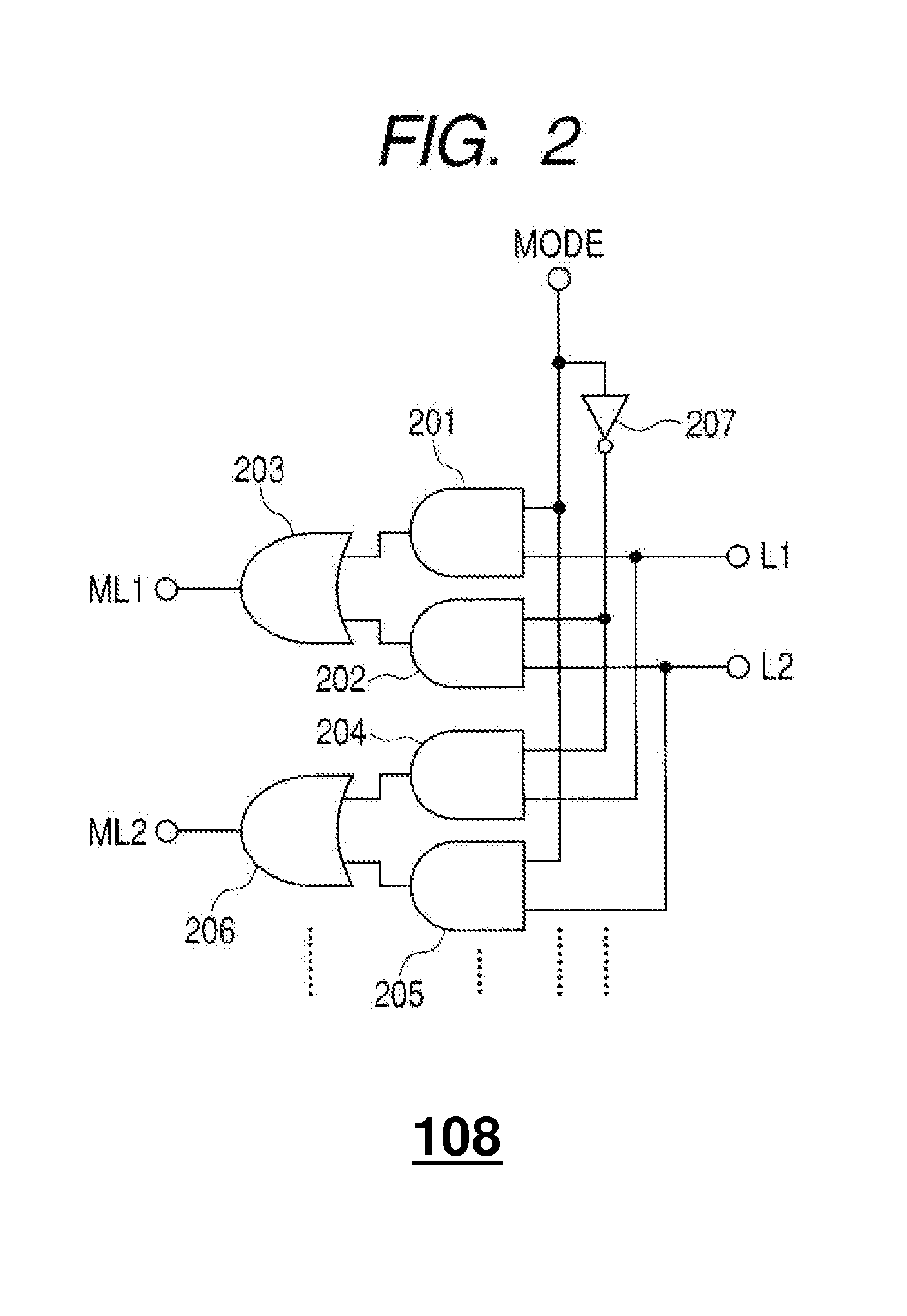
[0037]FIGS. 1A and 1B are a diagram illustrating block segmentation in an area-type AF sensor employing a photoelectric conversion apparatus according to a first embodiment of the present invention. The photoelectric conversion apparatus may comprise an area-type AF sensor as shown in FIG. 5 and a line selection switching circuit shown in FIG. 2, as an example.

[0038]FIG. 1A is a schematic diagrams for describing a first mode in the first embodiment, and FIG. 1B is a schematic diagram for describing a second mode in the first embodiment.

[0039]The area-type AF sensor illustrated in FIGS. 1A and 1B includes a first line sensor L1 group 101, a second line sensor L2 group 102, a first line memory L1 group 103 and a second line memory L2 group 104. The area-type AF sensor also includes a sensor drive circuit 105, a line selecting circuit 106, memory drive circuits 107 and a line selection switching circuit 108. A control circuit is formed by the sensor drive circuit 105, t...

Example

Second Embodiment

[0065]FIG. 4 is a schematic diagram of an optical system of a single-lens reflex camera equipped with a TTL-SIR (Through-The-Lens Secondary Image Registration) auto-focus system, which employs a photoelectric conversion apparatus for detecting focus according to an embodiment of the present invention. The camera illustrated in FIG. 4 includes a taking lens 40 for temporarily forming an image of a subject on a film or an image sensor, and a quick-return mirror 41 for reflecting light on a finder screen 42, which is a half mirror that transmits several tens of percent of light. The camera also includes a sub-mirror 43 for guiding light to the AF system, a photoelectric conversion apparatus for detecting focus 44, a secondary imaging lens (glass lens) 45 for re-forming an image of a subject on the AF sensor, a reflecting mirror 46 that guides light to the AF sensor 44, a focal plane shutter 47, and a film or image sensor 48. An optical axis 49 is also indicated in the ...


PUM


Abstract

Provided is a photoelectric conversion apparatus for detecting focus, which provides an increased number of ranging points while suppressing a chip-area increase. In a first mode, signals from a first line sensor L1 group are written in a first line memory L1 group while signals from a second line sensor L2 group are written in a second line memory L2 group. In a second mode, signals from the second line sensor L2 group are written in the first line memory L1 group while signals from the first line sensor L1 group are written in the second line memory L2 group, so that even one and the same line sensor can select different ranging point regions, enabling provision of an increased number of ranging points while suppressing a chip-area increase.

Description

BACKGROUND OF THE INVENTION[0001]1. Field of the Invention[0002]The present invention relates to a photoelectric conversion apparatus for detecting focus, which performs phase difference detection auto-focusing.[0003]2. Description of the Related Art[0004]Conventionally, for photoelectric conversion apparatuses for auto-focusing (AF) (auto-focus (AF) sensors), it has been proposed to switch effective regions in a sensor depending on the light-projection unit of the light source for ranging according to the scene to be shot, as indicated in Japanese Patent Application Laid-Open No. 2002-214516. Japanese Patent Application Laid-Open No. 2002-214516 describes that, for example, in a first ranging mode, focusing is performed by ranging one ranging point when light is emitted, and in a second ranging mode, focusing is performed by ranging seven ranging points when no light is emitted. In the art, various types of AF modes are employed to deal with scenes for which ranging is difficult to...

Claims


Application Information

Patent Timeline
IPC IPC(8): H01L27/00
CPCH01L27/14601H04N5/3692H04N5/23212H04N25/701
Inventor INOUE, DAISUKE
Owner CANON KK
Why Eureka
Try Eureka