Method and Apparatus of Providing Power to Ignite and Sustain a Plasma in a Reactive Gas Generator

a technology of reactive gas and plasma, which is applied in the direction of plasma technique, electric discharge tubes, light sources, etc., can solve the problems of unreliable operation and general reliability of techniques, and achieve the effect of less power and more power

Active Publication Date: 2010-09-02
MKS INSTR INC
View PDF40 Cites 262 Cited by
  • Summary
  • Abstract
  • Description
  • Claims
  • Application Information

AI Technical Summary

Benefits of technology

[0006]The invention features methods and power supplies that provide power to ignite and sustain a plasma in a reactive gas generator. Any of the particular embodiments described below can realize one or more of the following advantages. Embodiments can provide for a larger ignition space (e.g., a broader range of pressure and / or gas flows capable of igniting) with less complexity. In addition, embodiments can provide for a higher dQ / dt, which can allow for a large change of gas flow rate. Embodiments can eliminate or minimize the risk of anodization breakdown and punch-through. Embodiments can provide for reliable ignition and operation. Embodiments can increase block life. In addition, embodiments can provide for safe drop-out under all gas conditions.
[0010]In some embodiments, adjusting the power provided to the plasma ignition circuit can include adjusting a duty cycle and / or a frequency value of the ignition power supply. Adjusting the power provided to the plasma ignition circuit can be based on the difference between the measured pre-ignition signal and the adjustable pre-ignition control signal. Adjusting the power provided to the plasma ignition circuit can include providing less power to the plasma ignition circuit if the measured pre-ignition signal is greater than the adjustable pre-ignition control signal, and providing more power to the plasma ignition circuit if the measured pre-ignition signal is less than the adjustable pre-ignition control signal.

Problems solved by technology

However, such techniques are generally not reliable for the following reasons: arcing outside of the ignition window often occurs, punch through often occurs due to high loop and / or spark voltages, the operation is unreliable due to the use of one power train for control and monitoring, and large mismatches exist between impedances.

Method used


Image

  • Method and Apparatus of Providing Power to Ignite and Sustain a Plasma in a Reactive Gas Generator
  • Method and Apparatus of Providing Power to Ignite and Sustain a Plasma in a Reactive Gas Generator
  • Method and Apparatus of Providing Power to Ignite and Sustain a Plasma in a Reactive Gas Generator

Examples


Embodiment Construction

[0025]The invention features methods and power supplies that provide power to ignite and sustain a plasma in a reactive gas generator. Any of the particular embodiments described below can realize one or more of the following advantages. Embodiments can provide for a larger ignition space (e.g., a broader range of pressure and / or gas flows capable of igniting) with less complexity. In addition, embodiments can provide for a higher dQ / dt, which can allow for a large change of gas flow rate. Embodiments can eliminate or minimize the risk of anodization breakdown and punch-through within the plasma chamber. Embodiments can provide for reliable ignition and operation. Embodiments can increase block life. In addition, embodiments can provide for safe drop-out under all gas conditions.

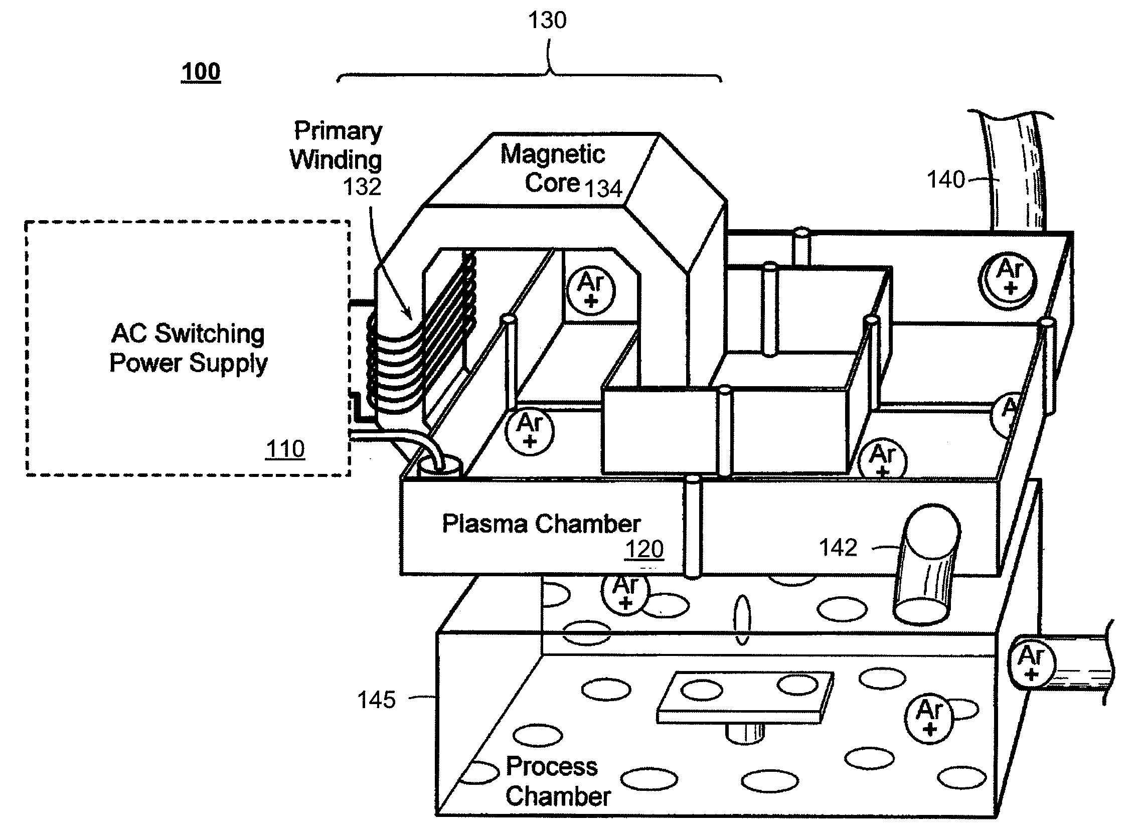
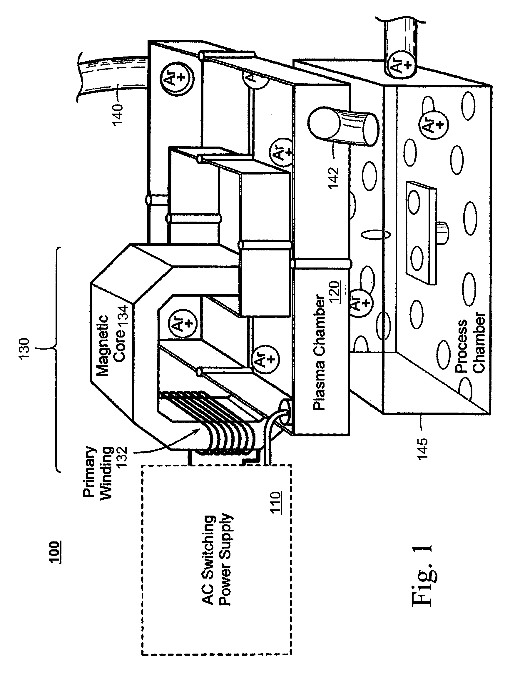
[0026]FIG. 1 is a diagram illustrating a reactive gas generator 100 to which embodiments of the invention can be applied. As illustrated, the reactive gas generator 100 includes a power supply 110 and a plas...


PUM


Abstract

Described are methods and apparatuses, including computer program products, for igniting and / or sustaining a plasma in a reactive gas generator. Power is provided from an ignition power supply to a plasma ignition circuit. A pre-ignition signal of the plasma ignition circuit is measured. The power provided to the plasma ignition circuit is adjusted based on the measured pre-ignition signal and an adjustable pre-ignition control signal. The adjustable pre-ignition control signal is adjusted after a period of time has elapsed.

Description

FIELD OF THE INVENTION[0001]The invention relates generally to the field of generating reactive gas containing ions, free radicals, atoms and molecules and to apparatuses for and methods of providing power for igniting and / or sustaining a plasma in a reactive gas generator.BACKGROUND OF THE INVENTION[0002]Plasma discharges can be used to excite gases to produce reactive gas containing ions, free radicals, atoms and molecules. Reactive gases are used for numerous industrial and scientific applications including processing solid materials such as semiconductor wafers, powders, and other gases.[0003]One example of a reactive gas is atomic fluorine, which can be used to clean chemical vapor deposition (CVD) chambers for deposition of thin films onto substrate surfaces. CVD chambers need to be routinely cleaned to remove the deposits that build up on the surfaces of chamber parts other than the substrate surfaces. Wet cleaning of a chamber is labor intensive and hazardous to workers, whi...

Claims


Application Information

Patent Timeline
Patent Type & Authority Applications(United States)
IPC IPC(8): H05H1/24
CPCH01J37/321H01J37/32009H05H1/36H01J37/32
Inventor BENZERROUK, SOUHEILNAGARKATTI, SIDDHARTH P.COWE, ANDREWSHAJII, ALIAMBROSINA, JESSE E.TRAN, KENCHEN, XING
Owner MKS INSTR INC
Why Eureka
Try Eureka