LED dimming apparatus
a technology of led dimming and led light, which is applied in the direction of electric variable regulation, process and machine control, instruments, etc., can solve the problems of large noise in the pulse current supplied to the led and varying the brightness of the ligh
- Summary
- Abstract
- Description
- Claims
- Application Information
AI Technical Summary
Benefits of technology
Problems solved by technology
Method used
Image
Examples
first embodiment
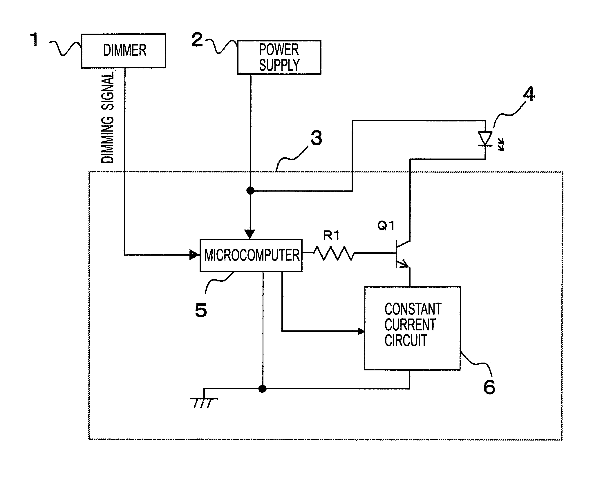
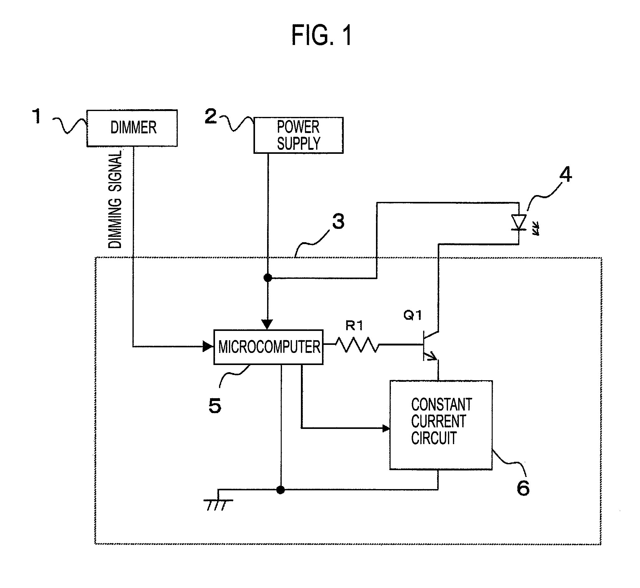
[0025]A circuit configuration of a first embodiment of the present invention is shown in FIG. 1. This embodiment is composed of: a dimmer 1, power supply 2; an LED lighting device 3; and an LED load 4. Moreover, the LED lighting device 3 is composed of: a microcomputer 5; a constant current circuit 6; a resistor R1; and a transistor Q1. The constant current circuit 6 is composed so as to flow therefrom a constant current designated by a signal from the microcomputer 5. The microcomputer 5 has functions to read a dimming signal from the dimmer 1, to control ON / OFF of the transistor Q1, and to set a current value of the constant current circuit 6.
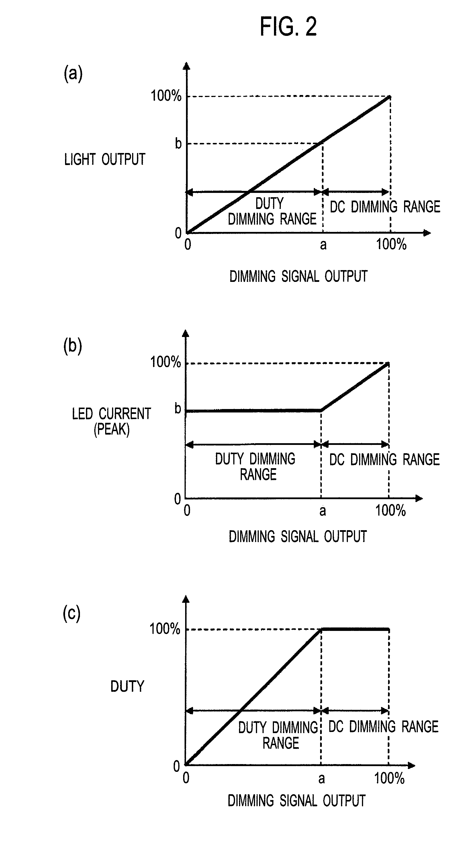
[0026]A predetermined dimming level (a) is stored in the microcomputer 5. In a range where a dimming degree is lower (where light is brighter), the microcomputer 5 fixes the transistor Q1 to be ON, and dims the light by changing a setting current of the constant current circuit 6. This refers to a DC dimming mode. In a range where the dimming...
second embodiment
[0034]A circuit configuration of a second embodiment of the present invention is shown in FIG. 4. This embodiment is composed of: the dimmer 1; the power supply 2; the LED lighting device 3; and the LED load 4. Moreover, the LED lighting device 3 is composed of: the microcomputer 5; the constant current circuit 6; resistors R1 and R2; and a semiconductor switching element Q1 such as a MOSFET.
[0035]The constant current circuit 6 is composed so as to flow therefrom the designated constant current in accordance with a voltage signal from the microcomputer 5. The microcomputer 5 has functions to read the dimming signal from the dimmer 1, to control ON / OFF of the transistor Q1, and to set a current value of the constant current circuit 6. The dimming signal from the dimmer 1 is a DMX signal generally used in lighting. However, the DMX signal only has 256 levels (1 byte), and is insufficient for dimming the LED load 4. Hence, in order to make smooth light dimming in which the brightness o...
third embodiment
[0048]FIG. 8 is a circuit diagram showing an overall configuration of a third embodiment of the present invention. In this embodiment, a lighting circuit of the LED load 4 is composed of a flyback-type DC-DC converter 10 including two feedback control circuits 11 and 12. A description will be made below of a circuit configuration of the lighting circuit.
[0049]To alternating current input terminals 21 and 22 connected to a commercial power supply (AC 100 V, 50 / 60 Hz), an overvoltage protection element ZNR is connected in parallel, and alternating current input terminals of a diode bridge DB are connected. A smoothing capacitor C1 is connected in parallel to direct current output terminals of the diode bridge DB.
[0050]To the smoothing capacitor C1, a primary winding of an insulating transformer T1 is connected through output terminals Q and G of a drive circuit 14. The drive circuit 14 incorporates a power MOSFET (not shown) between the output terminals Q and G thereof. The drive circ...
PUM
 Abstract
Description
Claims
Application Information
 - R&D
- Intellectual Property
- Life Sciences
- Materials
- Tech Scout
- Unparalleled Data Quality
- Higher Quality Content
- 60% Fewer Hallucinations
Browse by: Latest US Patents, China's latest patents, Technical Efficacy Thesaurus, Application Domain, Technology Topic, Popular Technical Reports.
© 2025 PatSnap. All rights reserved.Legal|Privacy policy|Modern Slavery Act Transparency Statement|Sitemap|About US| Contact US: help@patsnap.com


