Motor drive circuit

a technology of motor drive and circuit, which is applied in the direction of motor/generator/converter stopper, electronic commutator, dynamo-electric converter control, etc., can solve the problems of circuit protection or torque limitation of current flowing through the coil of the motor, and achieve the effect of easy generation

Inactive Publication Date: 2010-09-02
ROHM CO LTD
View PDF9 Cites 49 Cited by
  • Summary
  • Abstract
  • Description
  • Claims
  • Application Information

AI Technical Summary

Benefits of technology

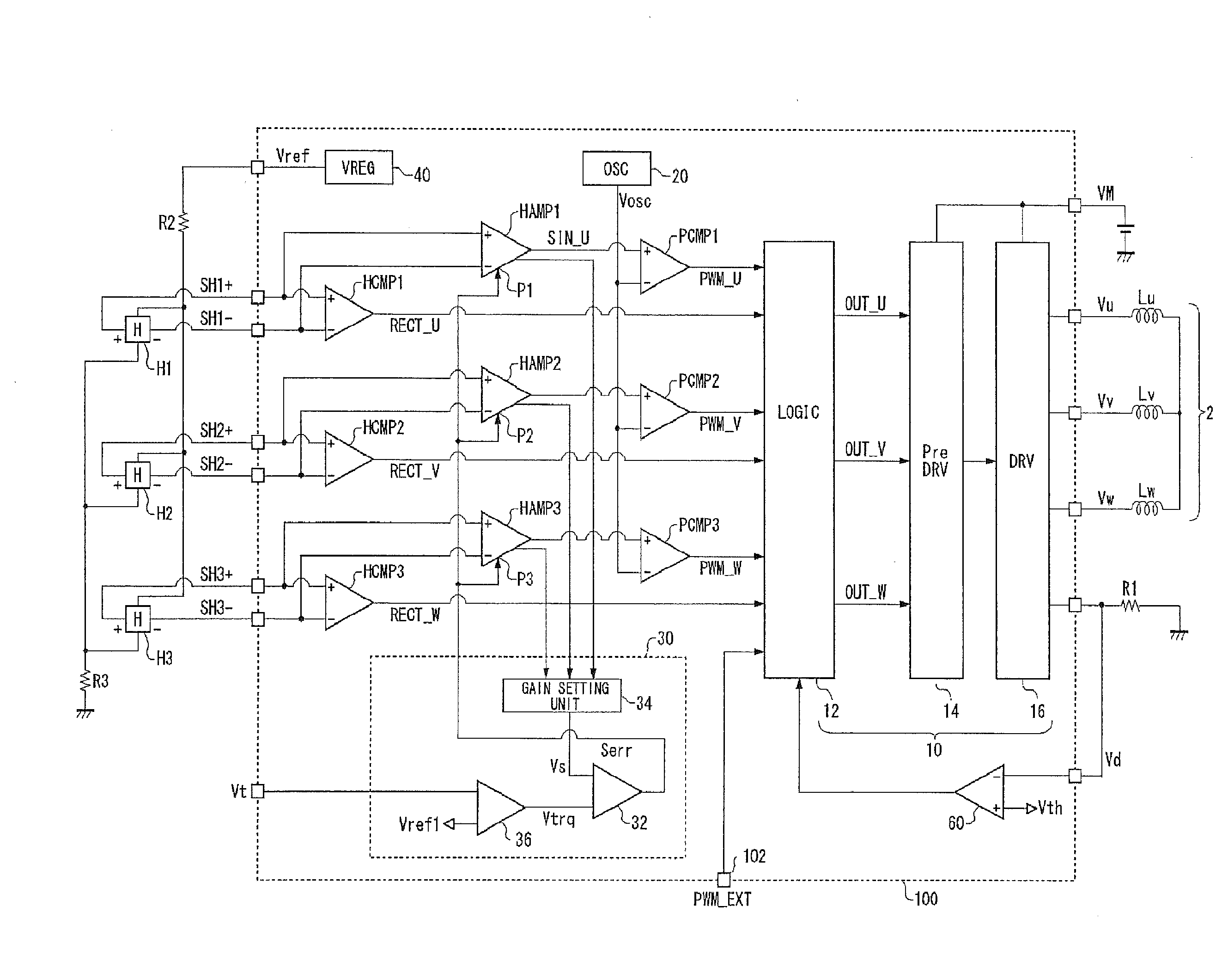
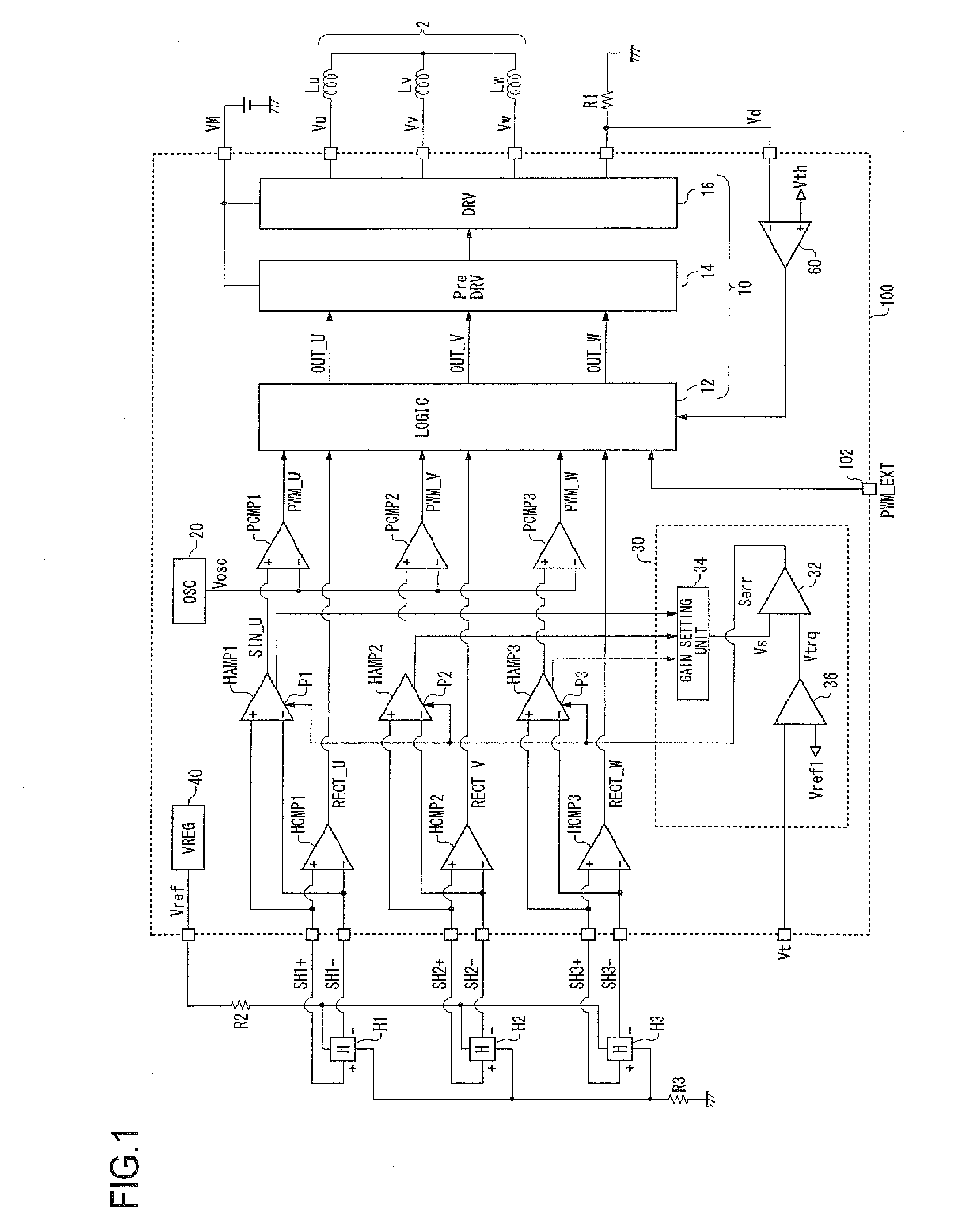
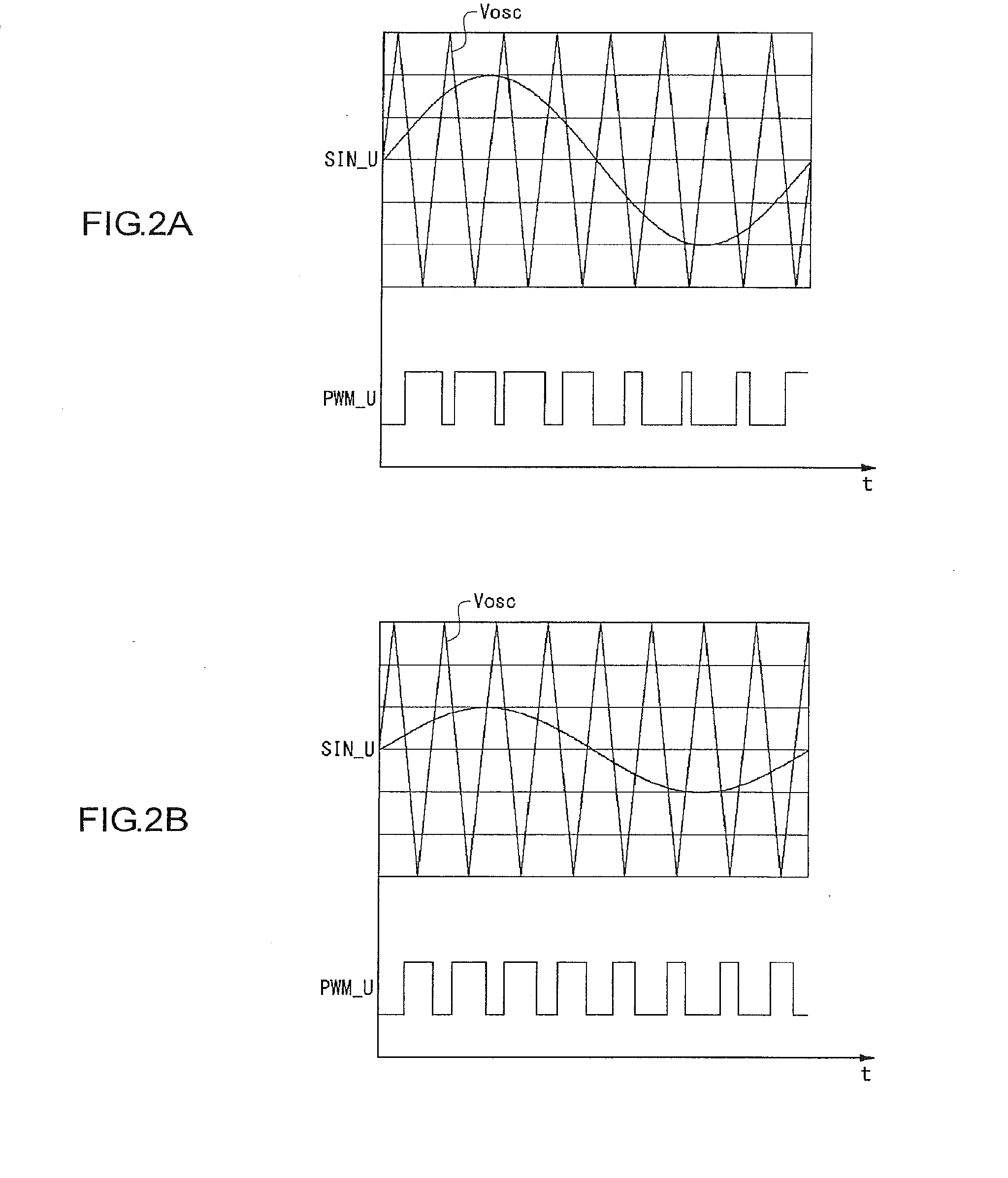
[0011]In the embodiment, the sine wave voltage outputted from each of the first Hall amplifier, the second Hall amplifier and the third Hall amplifier is determined based on the torque setting voltage, eventually allowing a duty ratio of the pulse modulated signal to be controlled based on the torque setting voltage. According to the embodiment, the sine wave voltage is not affected by the amplitude of the pair of Hall signals, allowing the motor to be rotated with a torque corresponding to the torque setting voltage.
[0030]After stopping excitation of each coil of the three-phase motor, the drive unit may release the stop of excitation based on a release signal having a predetermined cycle. The motor's continued stop of excitation can be prevented by periodically releasing the stop after the excitation is stopped, allowing the motor to be rotated again.
[0032]The release signal may be synchronized with a timing when the periodic voltage takes a peak value or a bottom value. When generating a triangle-shaped, or a saw tooth-shaped periodic voltage, a pulse signal whose level makes a transition at its peak and bottom is also generated. The release signal is readily generated by using the pulse signal.

Problems solved by technology

3. Also, it is sometimes required that a current flowing through a coil of the motor is to be limited in terms of circuit protection or torque limitation.

Method used


Image

  • Motor drive circuit
  • Motor drive circuit
  • Motor drive circuit

Examples


Embodiment Construction

[0050]The present invention will now be described based on preferred embodiments with reference to the accompanying drawings. The same or equivalent constituents, member, or processes illustrated in each drawing will be denoted with the same reference numerals, and the duplicative descriptions thereof are appropriately omitted. The preferred embodiments do not intend to limit the scope of the invention but exemplify the invention. All of the features and the combinations thereof described in the embodiments are not necessarily essential to the invention.

[0051]Herein, “the state where a member A is connected to a member B” includes not only the state where the member A is physically and directly connected to the member B but also the state where the member A is indirectly connected to the member B via another member that does not affect electrically the connection state between them. Likewise, “the state where a member C is provided between a member A and a member B” includes not onl...


PUM


Abstract

The motor drive circuit 100 supplies a drive current to the motor 2 to drive the motor. Each of the first Hall amplifier HAMP1 to the third Hall amplifier HAMP3 is provided for each phase of the motor 2 and receives a pair of Hall signals from a corresponding phase Hall element to generate each phase sine wave voltage SIN_U, SIN_V and SIN_W by amplifying a difference between the pair of Hall signals. Each of the first PWM comparator PCMP1 to the third PWM comparator PCMP3 is provided for each phase of the motor 2 and compares the corresponding phase sine wave voltage SIN_U, SIN_V and SIN_W with the periodic voltage Vosc to generate each phase PWM signal PWM_U, PWM_V and PWM_W. The drive unit 10 subjects a phase coil, a target to be driven, to pulse drive by using the pulse modulated signal from the corresponding PWM comparator.

Description

CROSS REFERENCE TO RELATED APPLICATIONS[0001]This is a U.S. national stage application of International Application No. PCT / JP2008 / 003005, filed on 23 Oct. 2008. Priority under 35 U.S.C. §119 (a) and 35 U.S.C. §365(b) is claimed from Japanese Application Nos. JP2007-275748, filed 23 Oct. 2007, JP2007-275758, filed 23 Oct. 2007, and JP 2007-275760, filed 23 Oct. 2007, the disclosures of which are also incorporated herein by reference.BACKGROUND OF THE INVENTION[0002]1. Field of the Invention[0003]The present invention relates to a motor drive circuit that controls rotation of a motor.[0004]2. Description of the Related Art[0005]Brushless direct current (DC) motors are used for rotating cooling fans or disk-type media. A brushless DC motor generally comprises a rotor provided with a permanent magnet and a stator provided with multiple phase coils connected together in a star connection. The coil is excited by controlling a current supplied thereto such that the rotor is driven by rela...

Claims


Application Information

Patent Timeline
Patent Type & Authority Applications(United States)
IPC IPC(8): H02P6/16
CPCH02P6/085H02P27/08H02P6/14H02P2209/09Y10S388/9072Y10S388/912
Inventor KUWAMURA, MAKOTO
Owner ROHM CO LTD
Why Eureka
Try Eureka