Amplifier circuit

a technology of amplifier circuit and amplifier, which is applied in the direction of low frequency amplifier, gain control, digital/coded signal control, etc., can solve the problems of large amount of power expended by amplifier, distortion of signal, and worse distortion of delayed signal

Active Publication Date: 2010-09-02
CIRRUS LOGIC INC
View PDF22 Cites 25 Cited by
  • Summary
  • Abstract
  • Description
  • Claims
  • Application Information

AI Technical Summary

Problems solved by technology

That is, a large amount of power is still being expended by the amplifier 10 even when the output signal Sout is small.
However, analogue delays often cause distortion of the signal; the longer the delay that is required, the worse the distortion of the delayed signal.
However, this approach also has drawbacks.

Method used


Image

  • Amplifier circuit
  • Amplifier circuit
  • Amplifier circuit

Examples


Embodiment Construction

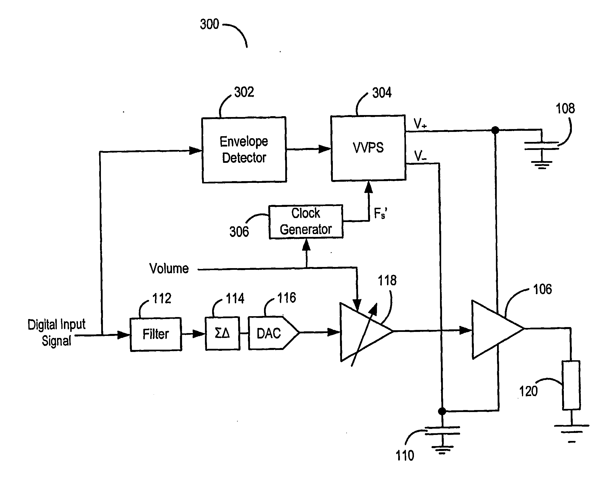
[0038]FIG. 6 shows an amplifier 100 for use in amplifying audio signals according to one aspect of the present invention. However, it will be appreciated that the amplifier 100 can be used for amplifying many other types of signal.

[0039]The amplifier 100 receives a digital input signal to be amplified. The digital input signal is input to an envelope detector 102. The envelope detector 102 detects the size of the envelope of the digital input signal and outputs a control signal 103 to a variable voltage power supply (VVPS) 104. The control signal 103 output to the VVPS 104 is indicative of the size of the detected envelope. The VVPS 104 in turn provides two voltages V+ and V− to a power amplifier 106 by charging respective capacitors 108, 110. As the control signal 103 from the envelope detector 102 varies, the voltages V+ and V− supplied by the VVPS 104 vary such that a control signal indicative of a relatively large envelope will lead to a relatively high voltage supplied to the p...


PUM


Abstract

An amplifier circuit comprises an input, for receiving an input signal to be amplified; a preamplifier, for amplifying the input signal based on a variable gain; a power amplifier for amplifying the signal output from the preamplifier, and a variable voltage power supply for supplying one or more supply voltages to the power amplifier. The supply voltages are adjusted based on the variable gain or the input digital signal. According to other aspects of the invention, a power supply of an amplifier circuit is clocked using a clock signal, whereby the clock signal has a frequency that varies in accordance with a volume signal or an input signal.

Description

[0001]This invention relates to amplifier circuits, and in particular but not exclusively to amplifier circuits that include power amplifiers.BACKGROUND[0002]FIG. 1 shows a basic Class AB amplifier 10. A bipolar (i.e. split level) power supply outputs the voltages V+, V− and these output voltages are applied across the amplifier 10, which amplifies the input signal Sin and outputs a ground-referenced amplified output signal Sout to a load 20. Provided the voltages supplied to the amplifier 10 are sufficient, the amplifier 10 has a substantially linear amplification (ignoring crossover effects). That is, the voltages V+, V− output from the power supply must be adequate so as to avoid output signal “clipping”, i.e. attenuation of the output when the signal nears, equals or exceeds the voltages V+, V− output from the power supply to the amplifier. This is avoided by having “headroom” between the maximum output signal Soutmax and the power supply rails.[0003]FIG. 2 is a graph showing So...

Claims


Application Information

Patent Timeline
Patent Type & Authority Applications(United States)
IPC IPC(8): H03G3/20
CPCH03F1/0227H03F1/0261H03G3/001H03F3/193H03F3/185H03F1/30H02M3/07H03F1/0211H03F1/0222H03F1/025H03F1/0266H03F1/26H03F3/213H03G3/002H03F1/02H03F1/0216H03F2200/03H03F2200/504H03G3/3015
Inventor LESSO, JOHN PAUL
Owner CIRRUS LOGIC INC
Why Eureka
Try Eureka