Flat heat pipe radiator and application thereof

a heat pipe radiator and radiator technology, applied in the direction of electrical apparatus casings/cabinets/drawers, electrical devices, instruments, etc., can solve the problems of manufacturing costs, achieve the effect of reducing the size of the fin, reducing the distance between the vaporizing area and the condensing area of the heat pipe, and intensifying the heat transfer structur

Inactive Publication Date: 2010-09-02
QIN BIAO
View PDF12 Cites 64 Cited by
  • Summary
  • Abstract
  • Description
  • Claims
  • Application Information

AI Technical Summary

Benefits of technology

[0008]In order to conquer the disadvantages of the above, the present invention changes the position of the fin, so the shell of the fan is left out, and the distance between the vaporizing area and the condensing area of the heat pipe is shortened; And intensified heat transfer structure

Problems solved by technology

The pin structure is not popular because of the high manufacturing cost, but the

Method used


Image

  • Flat heat pipe radiator and application thereof
  • Flat heat pipe radiator and application thereof
  • Flat heat pipe radiator and application thereof

Examples


Embodiment Construction

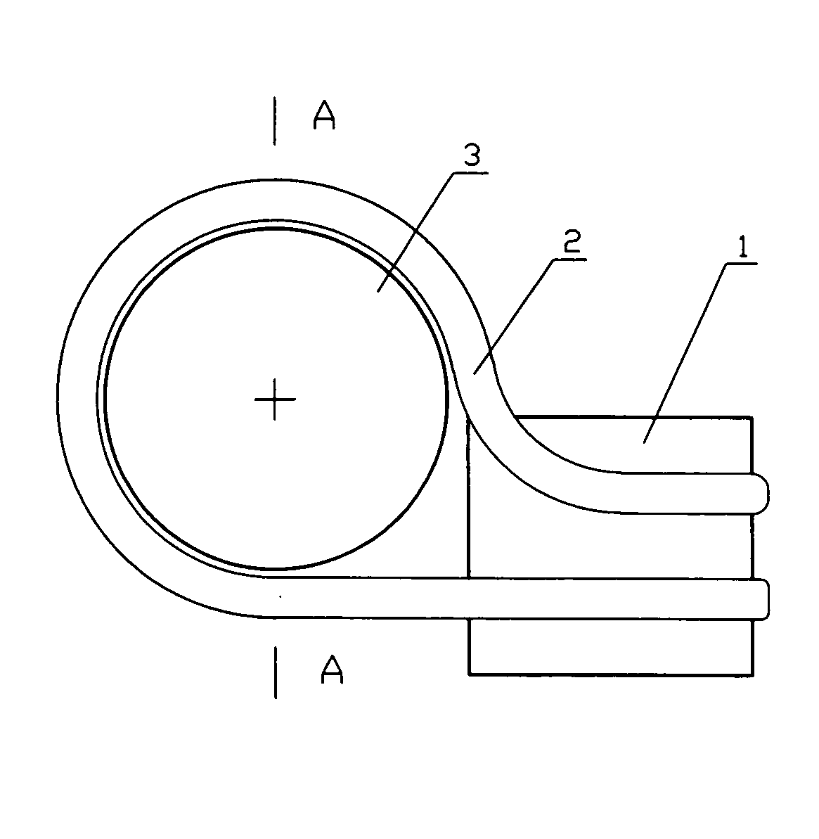
[0043]FIG. 1 shows the characteristic structure of one kind of the present invention radiator with tubular type of tubular structure heat pipe, wherein an air convective extended heat exchange surface is not shown in the FIG. 1. The heat pipe 2 surrounding impeller 3 is one integrative pipe, and its both ends are vaporizing segment which is on the back of conduction block 1. There is an even surface called heat-absorbing surface on the obverse side of conduction block 1.

[0044]Usually the welding or mosaic technology is adopted to set the vaporizing segment of the heat pipe with the conduction block together, for decreasing the contact thermal resistance; Conduction block 1 abuts against impeller 3 to cut down the distance between vaporizing area and condensing area effectually. Because of the limit of bending radius, the heat pipe can not be bended to surround the whole impeller) (360°, there is an opening near the conduction block 1, as FIG. 1 shows, one end of pipe 2 is extended s...


PUM


Abstract

A flat radiator with flat type heat pipe and its application for portable computers is provided. The heat pipe in a radiator use tubular type and plate type structures. An air convective extended heat exchange surface surrounds and is over against the fan impeller, such that the radiator is extremely compacted, and the heat transport distance in heat pipe is shortened. Further introducing enhanced convective heat transfer structure and setting the fins according to the aerodynamics improve the heat dissipating capacity. The restrictions to a radiator when installing are reduced, which helps to implement the standardization of the radiator series. Also portable computers using the radiator are provided.

Description

BACKGROUND OF THE PRESENT INVENTION [0001]1. Field of Invention[0002]The present invention relates to an electronic heat dissipating device, and more particularly to a flat radiator with heat pipe and centrifugal fan for using in portable electronic devices, such as for cooling the electronic chips (CPU or GPU) in portable (notebook) computer.[0003]2. Description of Related Arts[0004]As the higher demands of thinner and multi-functional portable devices, especially the CPU and GPU, the thermal design for the heat dissipating of the whole system has become a bottleneck to the improvement of portable computer's performance. The radiator affixed to the CPU or GPU is like the shell on a snail, and it has occupied quite much room of the portable computer, so cutting down the thickness of portable computer is restricted by the radiator.[0005]The structure of the radiator of current notebook computer is as following. It has a centrifugal fan with a shell, which is usually a helicoid shaped...

Claims


Application Information

Patent Timeline
IPC IPC(8): G06F1/20F28D15/04
CPCG06F1/203G06F2200/201H01L23/427H01L23/467G06F1/1635G06F1/1681G06F1/1667F28D15/02H01L2924/0002H01L2924/00F28D15/0233F28D15/0275
Inventor QIN, BIAO
Owner QIN BIAO
Why Eureka
Try Eureka