
Optical Information Recording Medium, Reproducing Device for Optical Information Recording Medium, Control Method and Control Program for the Reproducing Device, and Medium with the Control Program Recorded Therein

Inactive Publication Date: 2010-09-02
SHARP KK
View PDF41 Cites 43 Cited by
  • Summary
  • Abstract
  • Description
  • Claims
  • Application Information

AI Technical Summary

Benefits of technology

[0028]According to the arrangement, in a recordable / reproducible super-resolution optical information recording medium according to the present invention, a shortest pre-pit length in the pre-pits in which the medium identification information is recorded is longer than a shortest recording mark length in the recording marks in the first area. Therefore, in a case where the medium identification information is reproduced by a reproduction device having an optical system of which its resolution limit is not longer than or around a length of the shortest recording mark length in the recording marks in the first area, it is possible to reproduce the medium identification information with reproduction laser power optimum for the regular optical information recording medium. Thus, it is possible to realize a super-resolution optical information recording medium capable of identifying the optical information recording medium as a super-resolution optical information recording medium by use of reproduction laser power optimum for a regular optical information recording medium.
[0032]According to the arrangement, a shortest pre-pit length in the pre-pits in which the medium identification information is recorded, in a super-resolution optical information recording medium only for reproduction according to the present invention, is longer than a shortest recording mark length in the recording marks in the first area. Therefore, in a case where the medium identification information is reproduced by a reproduction device having an optical system of which its resolution limit is not longer than or around a length of the shortest recording mark length in the recording marks in the first area, it is possible to reproduce the medium identification information with reproduction laser power optimum for the regular optical information recording medium. Thus, it is possible to realize a super-resolution optical information recording medium capable of identifying the optical information recording medium as a super-resolution optical information recording medium by use of a reproduction laser power optimum for a regular optical information recording medium.
[0034]By having the above arrangement, the reproducing device is capable of identifying whether or not a provided optical information recording medium is the super-resolution optical information recording medium, by use of reproduction light power suitable for the regular optical information recording medium, accurately and with ease. Thus, it is possible to realize a reproducing device capable of reproducing both the super-resolution optical information recording medium and the regular optical information recording medium. Since the identification is carried out by use of reproduction light power suitable for the regular optical information recording medium, electricity consumption of the reproduction device is reduced. Furthermore, no breakage of the regular optical information recording medium occur due to reproduction light power optimum for the super-resolution optical information recording medium, since the identification is carried out by use of reproduction light power suitable for the regular optical information recording medium.

Problems solved by technology

However, in such a case, the medium identification information in the super-resolution medium 71 may not be reproducible, thereby causing a problem that no identification can be carried out.
However, excessive time is required since the switching of the reproduction laser power is carried out after the determination is made.
As a result, a long time is required to start-up the reproducing device.
As a result, this may cause a breakage problem of the regular medium 61.

Method used


Image

  • Optical Information Recording Medium, Reproducing Device for Optical Information Recording Medium, Control Method and Control Program for the Reproducing Device, and Medium with the Control Program Recorded Therein
  • Optical Information Recording Medium, Reproducing Device for Optical Information Recording Medium, Control Method and Control Program for the Reproducing Device, and Medium with the Control Program Recorded Therein
  • Optical Information Recording Medium, Reproducing Device for Optical Information Recording Medium, Control Method and Control Program for the Reproducing Device, and Medium with the Control Program Recorded Therein

Examples


embodiment 1

[0056]One embodiment of the present invention is described below with reference to FIGS. 1 through 3. The present embodiment is described by having a super-resolution optical information recording medium only for reproduction of which its cross sectional arrangement is of a BD type (hereafter referred to as a super-resolution medium 1) discussed as an example. In the following description, a reproducing device 10 denotes an optical information recording medium reproducing device 10 later described, capable of reproducing both the super-resolution medium 1 according to the present embodiment and a regular optical information recording medium.

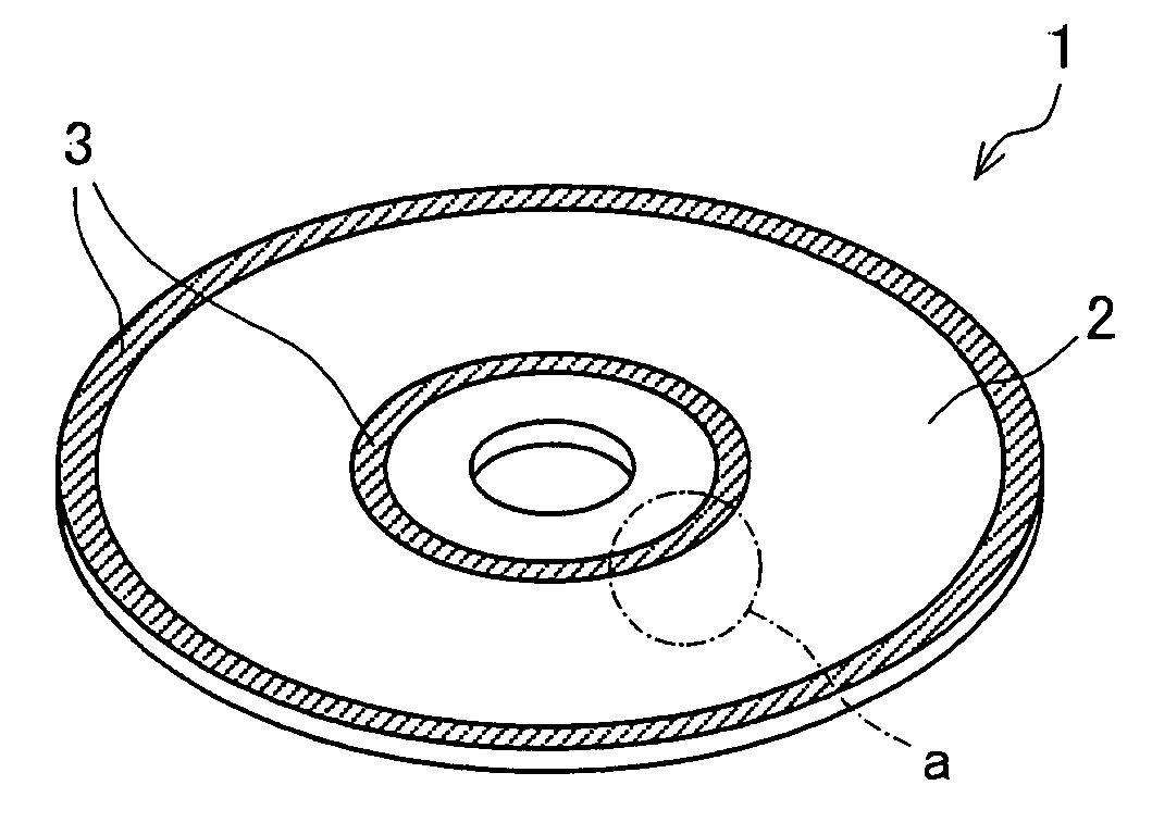
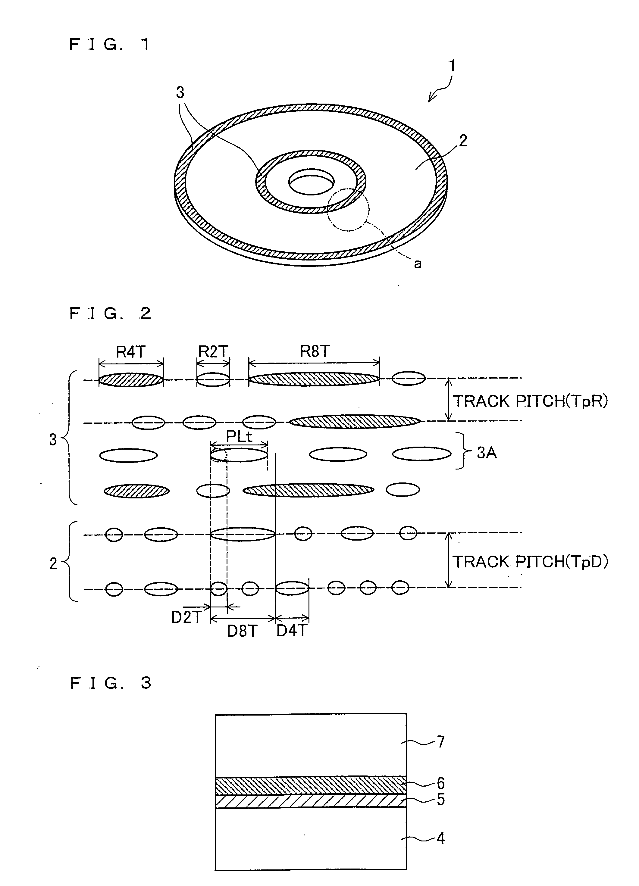
[0057]FIG. 1 illustrates an outer appearance of the super-resolution medium 1 according to the present embodiment.

[0058]FIG. 2 illustrates an enlarged view of section a in the super-resolution medium 1. A pre-pit having a length R2T shown in FIG. 2 is a shortest pre-pit in (i) a test read area 3A later described and (ii) a medium information area...

second embodiment

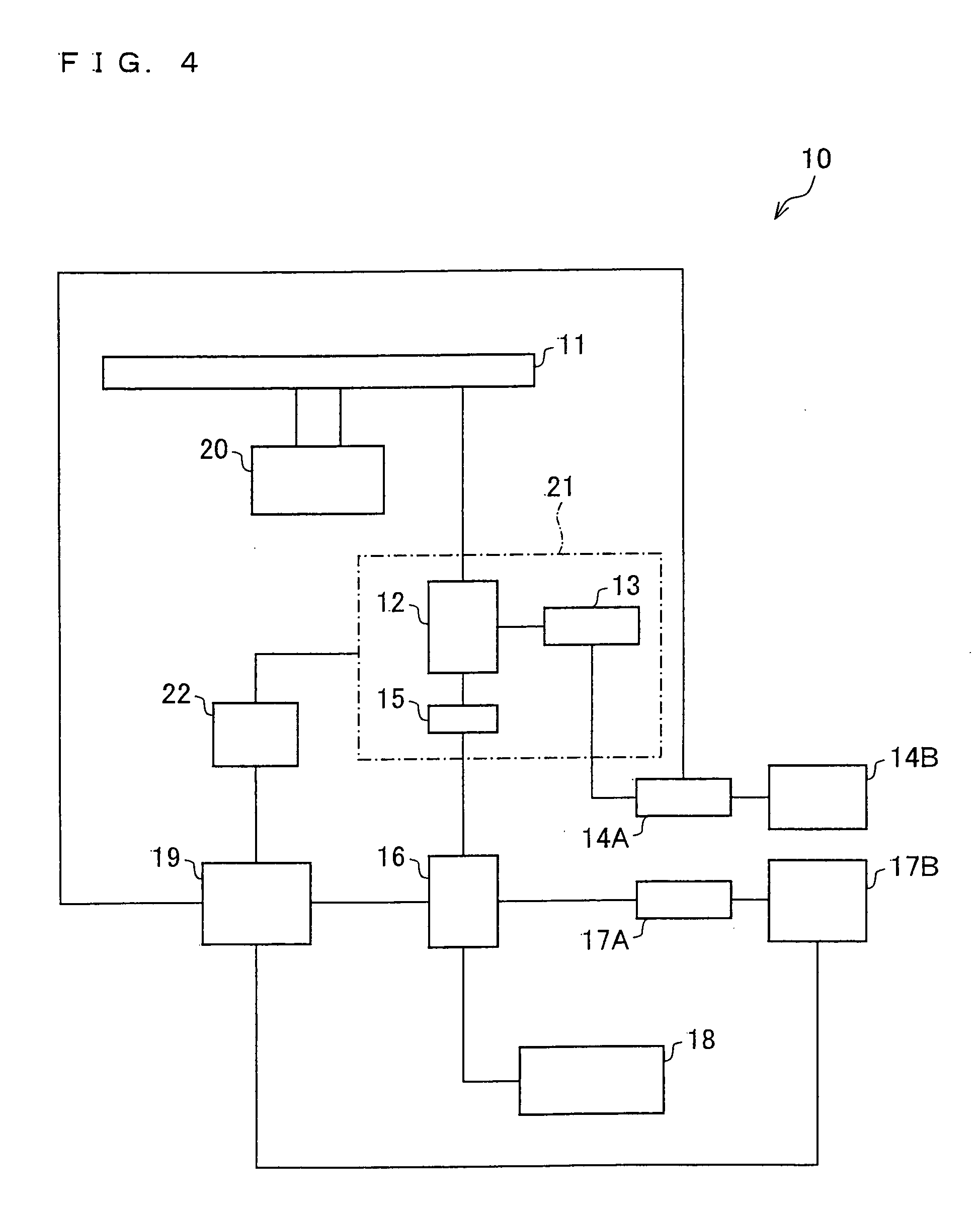
[0086]The following description explains another embodiment of the present invention, with reference to FIGS. 4 through 6. FIG. 4 schematically illustrates an arrangement of a reproducing device 10 according to the present embodiment. The reproducing device 10 of the present embodiment is capable of reproducing both the super-resolution medium 1 of First Embodiment and a regular medium.

[0087]The reproducing device 10 includes a laser control circuit 14A, a signal processing circuit 14B, a head amplifier 16, an RF amplifier 17A, a signal processing circuit 17B of an RF signal, a servo processing circuit 18, a control section 19 (control means), a spindle motor 20, a light pickup 21 (reproduction means), and a light pickup motor 22, as illustrated in FIG. 4. The light pickup 21 includes a polarization beam splitter 12, a laser light source 13, and a detector 15. An optical information recording medium 11 shown in FIG. 4 may be the super-resolution medium 1 or may be a regular medium.

[...


PUM


Abstract

A super-resolution medium (1) has a medium identification information for specifying a type of medium recorded in a medium information area (3) by use of pre-pits having a length not shorter than a length of a resolution limit of an optical system in a reproducing device (10).

Description

TECHNICAL FIELD[0001]The present invention relates to an optical information recording medium in which information is to be recorded, a reproducing device for the optical information recording medium, a control method and a control program for the reproducing device, and a recording medium with the control program recorded therein.BACKGROUND ART[0002]Recently, in order to process a massive amount of information such as images, enhancement in information density has been sought for in recording and reproduction of an optical information recording medium. In view of this, super-resolution techniques have been proposed, which record and reproduce information by use of recording marks, or pre-pits that are formed by concave portions and / or protrusions, each of which lengths of the marks or the pre-pits are shorter than a resolution limit of an optical system in a reproducing device. In the description, an optical information recording medium which is reproducible by the super-resolution...

Claims


Application Information

Patent Timeline
IPC IPC(8): G11B20/10G11B7/24G11B7/24085G11B7/24097
CPCG11B7/00736G11B7/0079G11B7/243G11B7/24G11B7/24085G11B7/1267
Inventor TAJIMA, HIDEHARUYAMAMOTO, MASAKIMORI, GOTAKAMORI, NOBUYUKI
Owner SHARP KK
Learn More