Method and system for automated x-ray inspection of objects

a technology of x-ray inspection and object, applied in the field of non-destructive testing (ndt) of parts, can solve the problems of low inspection reliability, affecting the performance of these techniques, and prone to operator fatigue in manual inspection procedures

Inactive Publication Date: 2010-09-02
GENERAL ELECTRIC CO
View PDF10 Cites 79 Cited by
  • Summary
  • Abstract
  • Description
  • Claims
  • Application Information

AI Technical Summary

Benefits of technology

[0006]In accordance with an embodiment of the invention, an anomaly detection method for comparing a scanned object to an idealized object is provided. The anomaly detection method includes generating a three-dimensional reference model of the idealized object. The anomaly detection method further includes acquiring at least one two-dimensional inspection test image of the scanned object and determining a two-dimensional reference image from the three-dimensional reference model using multiple pose parameters estimated by a 3D-2D registration algorithm, wherein the two-dimensional reference image corresponds to the same view of the three-dimensional reference model of the idealized object as the view of the two-dimensional inspection test image of the scanned object. Finally, the anomaly detection method includes identifying one or more defects in the inspection test image via automated defect recognition technique.

Problems solved by technology

However, and as will be appreciated by those skilled in the art, owing to the structural complexity and large production volumes of these castings, the manual inspection procedure is often prone to operator fatigue and hence suffers from low inspection reliability.
However, the performance of these techniques is affected by variations caused by object structure or flaw morphology and these techniques generally require large training sets with labeled flaws to perform defect identification.
Additionally, a number of NDT techniques involving 3D scanning of objects and 3D image to 2D image registration, makes the process of anomaly detection slower and inefficient.

Method used


Image

  • Method and system for automated x-ray inspection of objects
  • Method and system for automated x-ray inspection of objects
  • Method and system for automated x-ray inspection of objects

Examples


Embodiment Construction

[0012]The present techniques are generally directed to automated anomaly detection, possibly in conjunction with computer assisted detection and / or diagnosis (CAD) algorithms. Such analysis may be useful in a variety of imaging contexts, such as industrial inspection system, nondestructive testing and others.

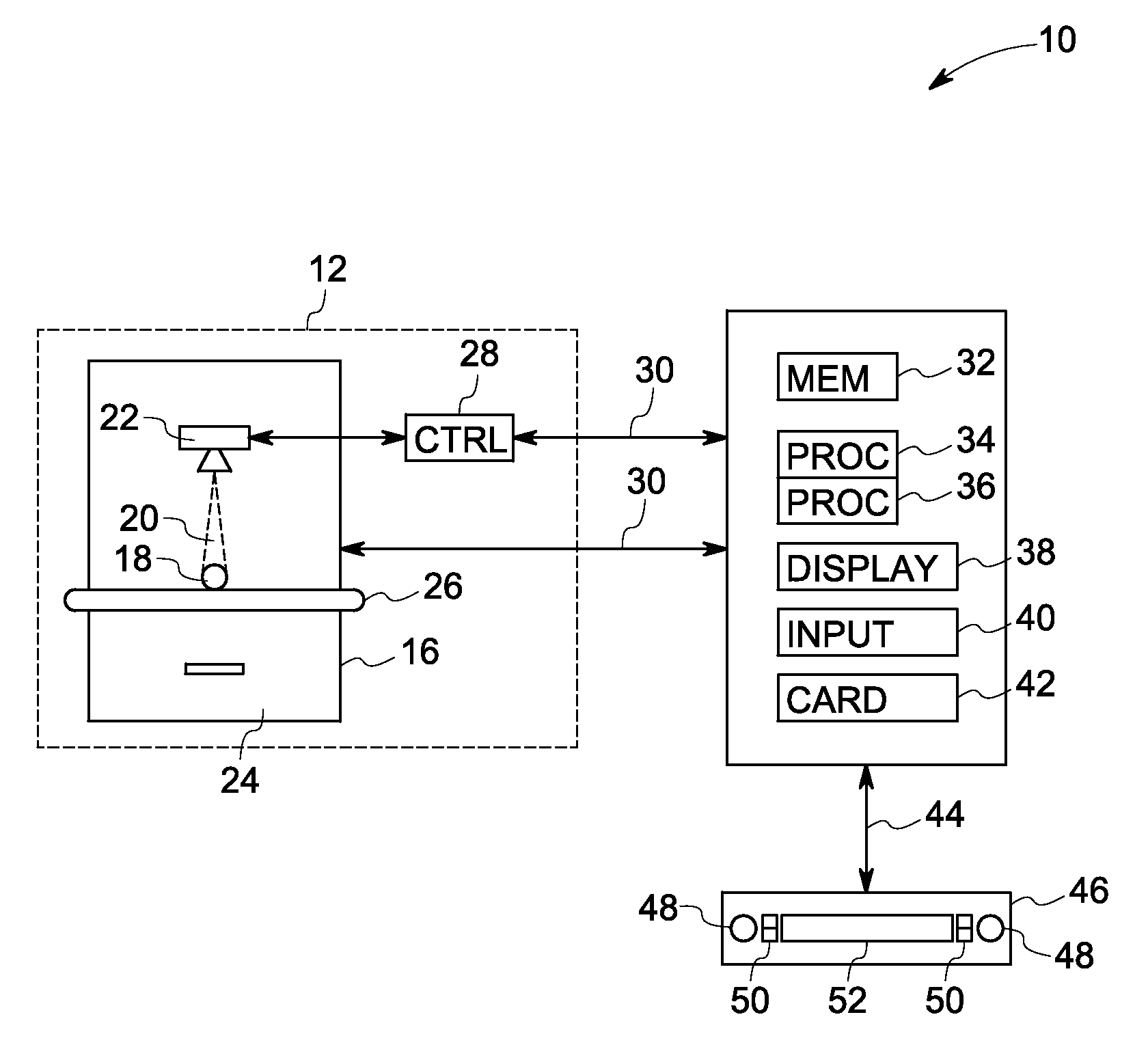
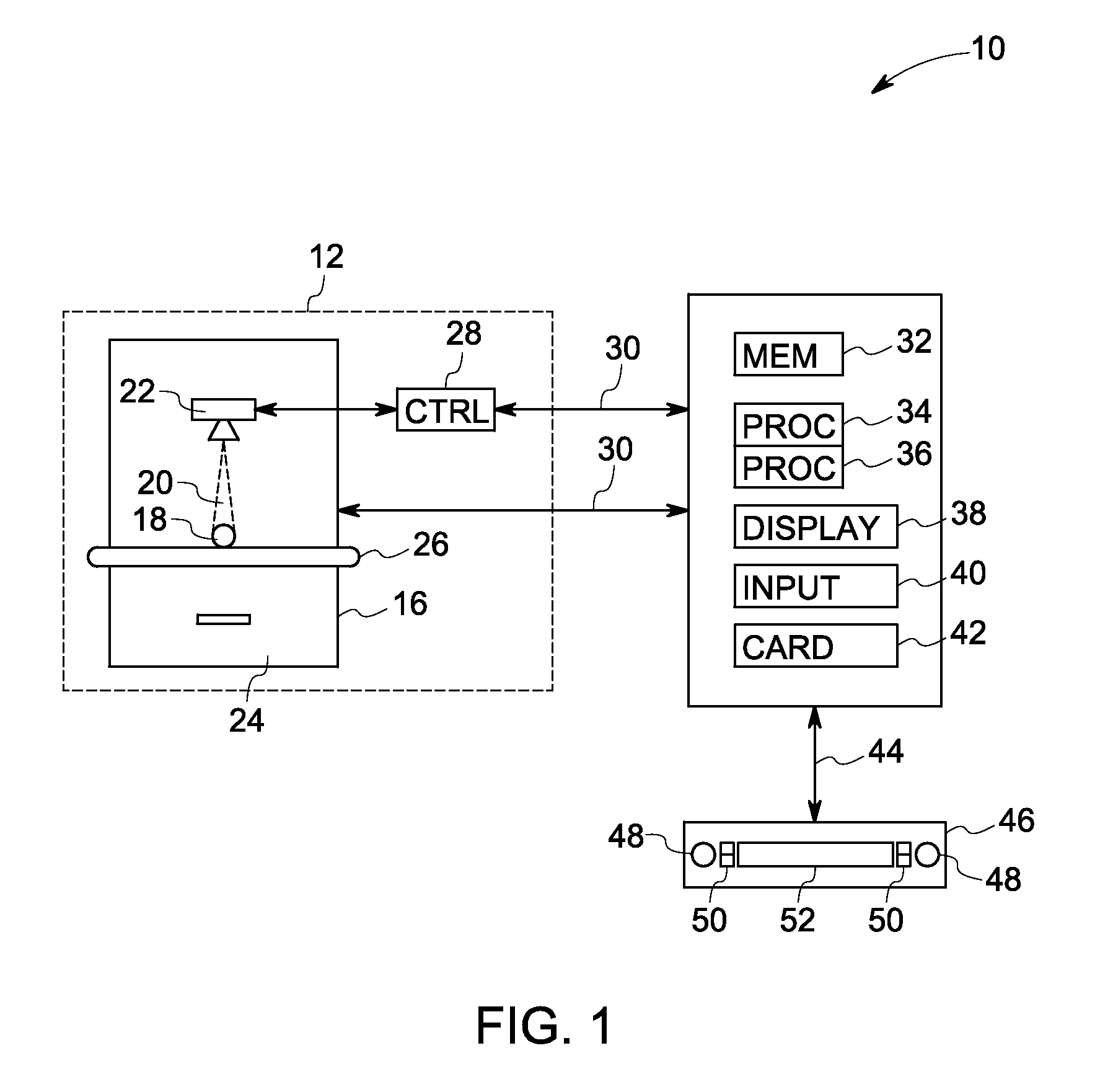
[0013]FIG. 1 is an illustration of an exemplary inspection system for processing an inspection test image data corresponding to a scanned object. It should be noted that although the illustrated example is directed to automated anomaly detection using x-ray inspection, the present invention is equally applicable to other inspection modalities, non-limiting examples of which include CT, infrared, eddy current, ultrasound and optical. Referring to FIG. 1, the inspection system 10 includes a computer system 14 adapted to be in signal communication with an imaging system 12 via a communication bus 30. A real-time image controller 46 is adapted to be in signal communication with the ...


PUM


Abstract

An anomaly detection method and system for comparing a scanned object to an idealized object is provided. The anomaly detection method includes generating a three-dimensional reference model of the idealized object. The anomaly detection method further includes acquiring at least one two-dimensional inspection test image of the scanned object. The anamoly detection method also includes determining a two-dimensional reference image from the three-dimensional reference model using multiple pose parameters, wherein the two-dimensional reference image corresponds to the same view of the three-dimensional reference model of the idealized object as the view of the two-dimensional inspection test image of the scanned object. The anamoly detection method further includes identifying one or more defects in the inspection test image via automated defect recognition technique.

Description

BACKGROUND[0001]The invention relates generally to nondestructive testing (NDT) of parts and more particularly to a method and system for automatically identifying defects in NDT image data corresponding to a scanned object.[0002]NDT is a technique of producing relevant data for an object by collecting energy emitted by or transmitted through the object, such as by penetrating radiation (gamma rays, X-rays, neutrons, charged particles, etc.) sound waves, or light (infrared, ultraviolet, visible, etc.). The manner by which energy is transmitted through or emitted by any object depends upon variations in object thickness, density, and chemical composition. The energy emergent from the object is collected by appropriate detectors to form an image or object map, which may then be realized on an image detection medium, such as a radiation sensitive detector. A radiographic detector, for example, comprises an array of elements that records the incident energy at each element position, and...

Claims


Application Information

Patent Timeline
Patent Type & Authority Applications(United States)
IPC IPC(8): G06K9/00
CPCG06T2207/10116G06T7/001
Inventor KAUCIC, ROBERT AUGUSTMILLER, JAMES VRADENBURGCAN, ALISUN, ZHAOHUITAO, XIAODONG
Owner GENERAL ELECTRIC CO
Why Eureka
Try Eureka