Carbon nanotube conductive layer using spray coating and preparing method thereof

a technology of conductive layer and carbon nanotube, which is applied in the direction of electrically conductive paint, instruments, transportation and packaging, etc., can solve the problems of inability to change the electrical properties of cnt transparent electrodes, inability to retain satisfactory transparency and condtutivity, etc., to improve transparency and conductivity, and simplify the generation procedure

Inactive Publication Date: 2010-09-02
TOP NANOSYS
View PDF1 Cites 11 Cited by
  • Summary
  • Abstract
  • Description
  • Claims
  • Application Information

AI Technical Summary

Benefits of technology

[0012]A loop pattern in which a plurality of loops which are created by a spray-coating method and are at least partially connected with one another allows a CNT transparent conductive layer to have significantly improved transparency and conductivity. Such the CNT transparent conductive layer has condtutivity and sheet resistance characteristics...

Problems solved by technology

Especially, a CNT transparent electrode coated on a plastic substrate is more resilient to an external impact or stress than an ITO transparent electrode which is a metal oxide thin layer, and thus the electronic properties of the CNT transparent electrode are not easily changed even when the substrate is bent or...

Method used


Image

  • Carbon nanotube conductive layer using spray coating and preparing method thereof
  • Carbon nanotube conductive layer using spray coating and preparing method thereof
  • Carbon nanotube conductive layer using spray coating and preparing method thereof

Examples


exemplary embodiment 1

[0054]Single-walled carbon nanotubes (SWNT) of 3.0 mg and a SDS dispersing agent of 1.5 mg are put in distilled water of 200 ml and they are evenly mixed together. The mixed material is dispersed for an hour by use of a bath sonicator (Branson 5510 at 40 kHz and 135 W), and then the dispersed material is used as a coating solution.

[0055]A polyethylene terephthalate (PET) film is used as a base. The base is placed on a heating plate heated at 70° C., and spray-coated with the coating solution by use of a spraying device (Anest Iwata W-100). Then the spray-coated base is dried out to fabricate a CNT transparent conductive layer. In this case, the coating solution is sprayed at a pressure of 5 kgf / cm2.

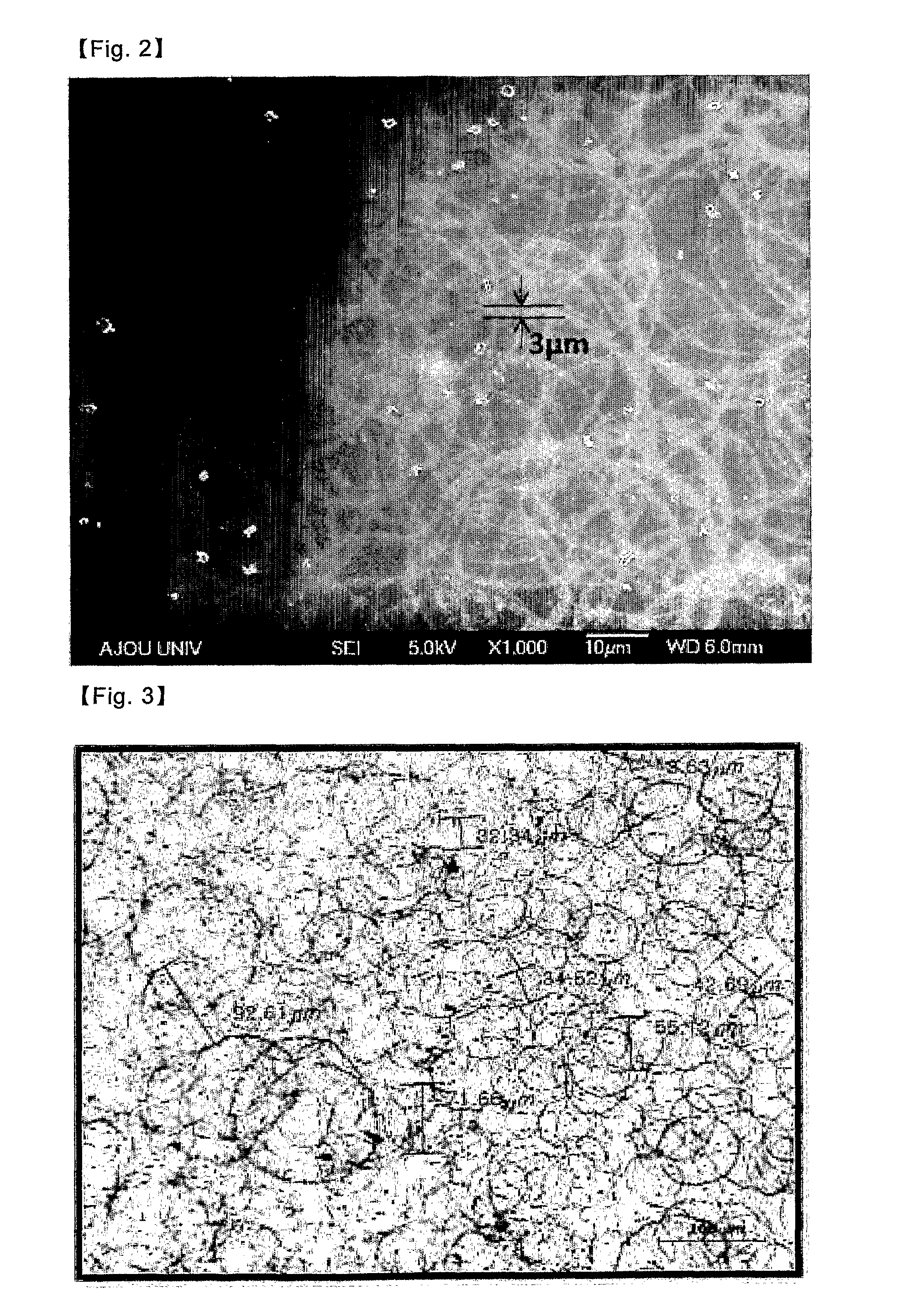
[0056]The fabricated CNT transparent conductive layer is enlarged by 200 times and observed by using a microscope (OLYMPUS BX51) as shown in FIG. 3. The sheet resistance and transparency of the CNT transparent conductive layer are measured and shown in Table 1 below.

[0057]Referring to FIG...

exemplary embodiment 2

[0058]3.0 mg of single-walled carbon nanotubes (SWNT), 1.5 mg of a SDS dispersing agent and 200 ml of distilled water are evenly mixed together.

[0059]The mixture is dispersed for an hour by use of a bath sonicator (Branson 5510 at 40 kHz and 135 W), and then the dispersed material is used as a coating solution.

[0060]A PET film is used as a base, and the film is heated by placing it on a heating plate heated at 70° C. Then, the base is spray-coated with the coating solution by use of an ultrasonic sprayer (from Samsung Electronics) by spraying the solution at a pressure of 1 kgf / cm2. Then the spray-coated base is dried up to fabricate the CNT transparent conductive layer.

[0061]The CNT transparent conductive layer fabricated in accordance with the current embodiment is enlarged by 200 times and observed, as shown in FIG. 4. The sheet resistance and transparency of the CNT transparent conductive layer are measured and listed on the Table 1 below.

[0062]Referring to FIG. 4, it can be con...


PUM

PropertyMeasurementUnit
Temperatureaaaaaaaaaa
Thicknessaaaaaaaaaa
Pressureaaaaaaaaaa

Abstract

Provided is a carbon nanotube (CNT) transparent conductive layer having a loop pattern in which a plurality of loops are at least partially connected to one another, and a fabrication method thereof. The loops in the pattern are generated by a spray-coating method and partially connected with one anther, and thus improving transparency and conductivity of the CNT transparent conductive layer. In Addition, the CNT transparent conductive layer has conductivity and sheet resistance highly suitable for a transparent electrode.

Description

TECHNICAL FIELD[0001]The present invention relates to a carbon nanotube (CNT) transparent conductive layer fabricated by spray-coating and a fabrication method thereof, and more particularly, to a CNT transparent conductive layer which has a spray pattern with high conductivity and transparency created thereon by adjusting a shape of the pattern while a base is coated with a carbon nanotube solution.BACKGROUND ART[0002]A carbon nanotube (CNT) consists of a plurality of carbon atoms arranged in a tube. The carbon atoms are arrayed in a hexagonal lattice, similar to a honeycomb. A diameter of the tube is as small as a nanometer, and has unique electrical, chemical properties.[0003]The carbon nanotube has advantageous mechanical properties, electrical selectivity, and remarkable field emission properties. The carbon nanotube may have semi-condtuctor properties according to arrangement of the carbon atoms, and the energy gap of the nanotube varies depending on the size of diameter of th...

Claims


Application Information

Patent Timeline
IPC IPC(8): H01B1/04B05D5/12D01F9/12C09D7/61
CPCH01J1/304Y10T428/30B05D1/02H01J2201/30469Y10T428/268C09D7/1291C09D5/24B05D3/0218H01B1/04C08K3/04H01B1/24H05K1/097H05K1/16H05K3/14H05K3/227H05K2201/026H05K2201/0323H05K2201/09681H05K2201/10053H05K2201/10128C09D7/70C09D7/61C08K3/041C09D7/66
Inventor OH, SANG KEUNSONG, KYOUNG HWAJEONG, DA JEONGPARK, DO HYEONGLEE, DONG-MYEON
Owner TOP NANOSYS
Why Eureka
Try Eureka