
Wall-mounted modular accessory system

Inactive Publication Date: 2010-09-09
RASPBERRY MED
View PDF42 Cites 51 Cited by
  • Summary
  • Abstract
  • Description
  • Claims
  • Application Information

AI Technical Summary

Benefits of technology

[0004]The present invention provides a wall-mounted modular accessory system that permits various panels and functional modules to be positioned along a framework for convenient usage at a defined location. The panels and modules are generally interchangeable and may be positioned substantially anywhere along the framework, and some of the panels or modules may be installed at the framework in different orientations. The framework may be adapted to mount other items via brackets that are received in channels along the framework, so that the items can be mounted alongside or between panels or modules. In addition, the framework may provide routing paths and retainers for wiring in order to provide an uncluttered appearance while facilitating access to the wiring along the framework and behind the various panels and modules. The panels and modules may be mounted to the framework by snap-fitting them into place without using any tools, and may be manually removed without tools, or with the aid of a simple pry bar or the like.
[0008]In yet another aspect, the first plurality of engaging members on the panels and the second plurality of engaging members on the functional modules are arranged in an evenly spaced manner. Optionally, the first and second pluralities of engaging members are evenly spaced in square (or repeating-square) patterns to facilitate installation of the panels and modules in multiple positions (and, optionally, in multiple orientations) along the framework.

Problems solved by technology

These devices are typically separate and distinct from one another, not conveniently or centrally located, and are not interchangeable, such that the area can become cluttered with devices, many of which may have power of data wires that need to be separately routed to respective power or data sources.

Method used


Image

  • Wall-mounted modular accessory system
  • Wall-mounted modular accessory system
  • Wall-mounted modular accessory system

Examples


Embodiment Construction

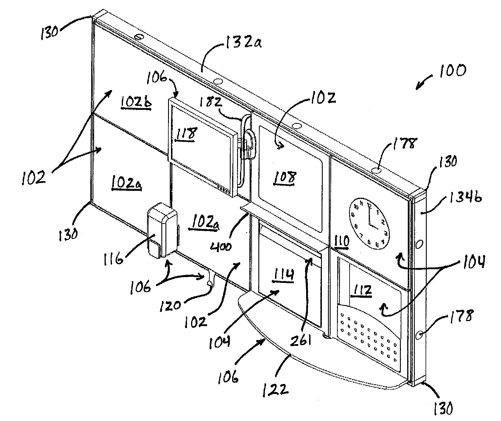
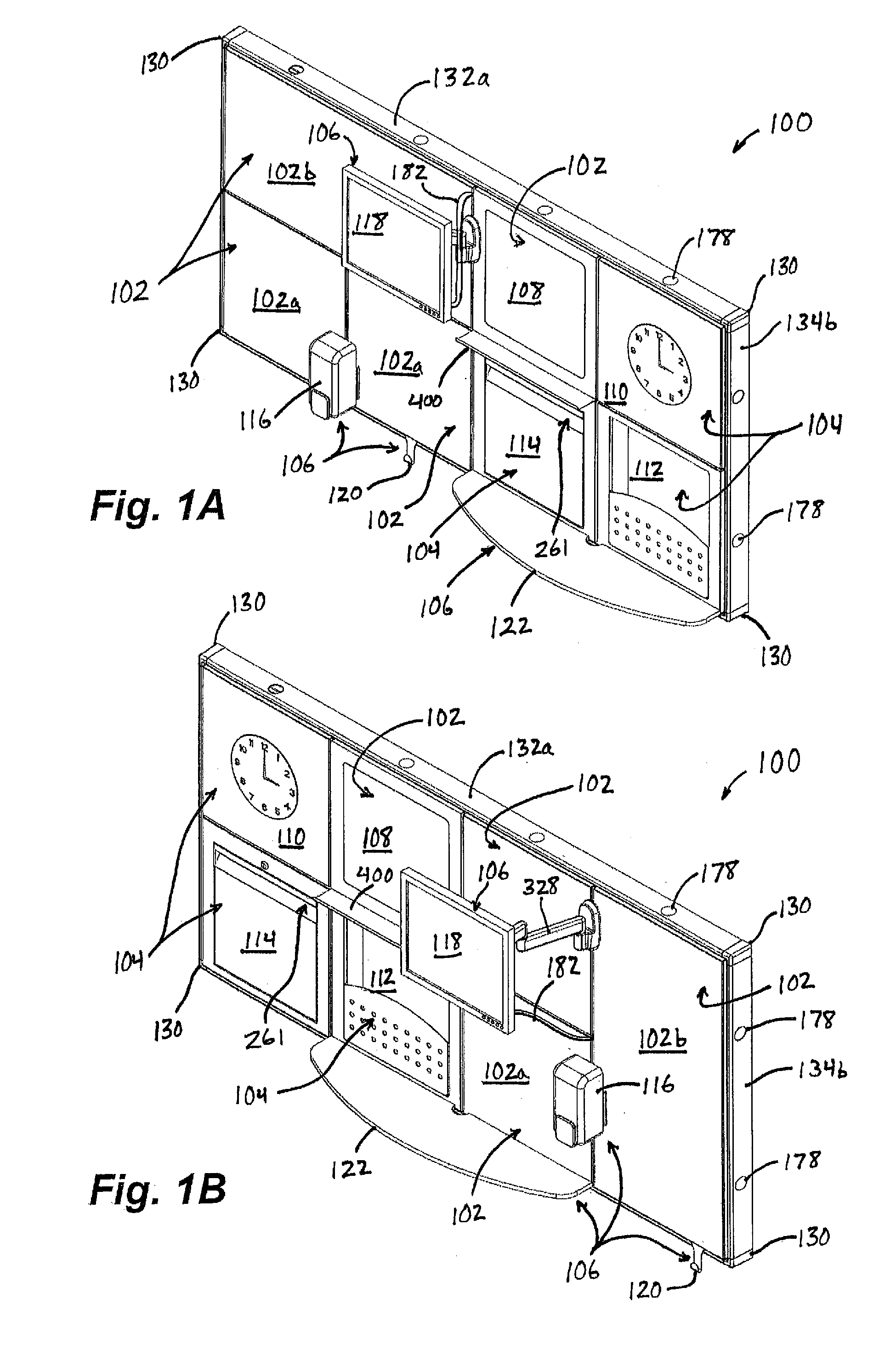
[0089]Referring now to the drawings and the illustrative embodiments depicted therein, a wall-mounted modular accessory system 100 supports a plurality of panels102, functional modules 104, and accessories 106 (FIGS. 1A and 1B). Panels 102 are repositionable along system 100, and further, are typically re-orientable by removing, rotating, and re-installing them in a manner described below. Functional modules 104 are also repositionable within the system, as are accessories 106, which are typically mounted alongside or in-between panels 102 and modules 104, as will be described in greater detail below. In the illustrated embodiment of FIGS. 1A and 1B, panels 102 include square decorative panels 102a and a rectangular decorative panel 102b, plus a marker board 108. Functional modules 104 include a clock module 110, a file storage module 112, and a lockable storage module 114. Accessories 106 include a soap dispenser 116, a television 118, a coat hook 120, and a shelf 122. As will be u...


PUM


Abstract

A modular accessory system is supportable on a vertical surface such as a wall, an office divider, or the like and includes a framework that support panels and / or functional modules to provide a desired appearance and / or functions for use in an area. The panels and modules are repositionable, and some may be oriented in two or more different orientations on the framework. Engaging members are provided at spaced intervals along each panel and module, with additional engaging members provided at spaced intervals along the framework. The engaging members along the framework releasably engage the engaging members on the panels and modules to support them on the framework. In addition, brackets may be coupled to the framework in either a vertical or horizontal orientation, such as alongside any panel or module, to support accessories thereon. Electrical wiring may be routed through the framework to supply certain panels, modules, or accessories.

Description

CROSS REFERENCE TO RELATED APPLICATION[0001]The present invention claims the benefit of U.S. provisional application Ser. No. 61 / 157,742, filed Mar. 5, 2009, which is hereby incorporated herein by reference in its entirety.FIELD OF THE INVENTION[0002]The present invention relates generally to modular accessory systems, and in particular, to wall-mounted modular accessory systems for providing various functions.BACKGROUND OF THE INVENTION[0003]Hospital rooms, meeting rooms, and other work areas are often equipped with many different devices that provide or perform various functions. For example, a typical hospital room may be equipped with a television, a clock, file storage, work / writing surfaces, computers, and the like. These devices are typically separate and distinct from one another, not conveniently or centrally located, and are not interchangeable, such that the area can become cluttered with devices, many of which may have power of data wires that need to be separately route...

Claims


Application Information

Patent Timeline
IPC IPC(8): E04F19/08E04C2/52E04B2/30
CPCA47B46/005A47B96/00A61G12/005A47B96/20E04F19/08A47B96/06
Inventor SUTTON, TODD A.BODKINS, NOEL J.
Owner RASPBERRY MED
Features
  • Generate Ideas
  • Intellectual Property
  • Life Sciences
  • Materials
  • Tech Scout
  • Unparalleled Data Quality
  • Higher Quality Content
  • 60% Fewer Hallucinations
Learn More