Heat exchange tube

a technology of heat exchange tube and projecting portion, which is applied in the direction of indirect heat exchanger, tubular elements, lighting and heating apparatus, etc., can solve the problems of inability to achieve sufficient increase in the surface area of inside and outside of the tube, decrease in the diameter of the projecting portion, etc., and achieve the effect of facilitating the formation of a plurality of projecting portions and enhancing heat exchange efficiency

Active Publication Date: 2010-09-09
YUTAKA GIKEN CO LTD +1
View PDF20 Cites 5 Cited by
  • Summary
  • Abstract
  • Description
  • Claims
  • Application Information

AI Technical Summary

Benefits of technology

[0006]A heat exchange tube facilitates formation of a plurality of projecting portions with the thickness hardly changed and without formation of protruded portions, and further is capable of contributing to enhancement of heat exchanging efficiency.
[0008]On the tube peripheral wall, a plurality of projecting portions which project to the inner surface side of the tube peripheral wall, and are formed by pushing, are formed into conical shapes across the tube axis, and therefore, the thickness of each of the projecting portions hardly differs from the thickness of the original peripheral wall. Accordingly, forming by pushing of each of the projecting portions can be easily performed, and workability is favorable. In addition, the surface areas of the inside and outside of the tube can be effectively increased by the conical projecting portions.
[0009]Further, a plurality of projecting portions are arranged along the virtual spirals on the tube peripheral wall, whereby the spiral flow path is formed in the tube. In addition, the sectional area of the flow path changes to become the minimum at the position of the vertex of each of the projecting portions, and become the maximum at the intermediate position between the adjacent projecting portions, and the gas which flows in the above described spiral flow path is effectively agitated by repeating expansion and contraction while turning, whereby heat exchange can be efficiently performed between the fluids inside and outside the tube.
[0010]Furthermore, by the inward conical projecting portions, outward projections are not formed on the tube peripheral wall, and therefore, interference with the other members of the tube is avoided, which can contribute to improvement in assembly property of the heat exchanger.
[0012]According to the second feature, when the fluid flowing in the flow path in the tube while turning moves from one axial area to the other axial area, the fluid inverses the turning direction. Therefore, agitation of the fluid can be performed more effectively, and the aforementioned heat exchange can be performed more efficiently.
[0014]According to the third feature, the spiral flow path in the tube can be reliably formed in each of the axial areas, and the agitation effect of the fluid can be enhanced.

Problems solved by technology

Incidentally, the projecting portion shown in FIG. 8 is unfavorable in workability since the thickness of the ridge portion of the projecting portion 031 inevitably increases more than the thickness of it before formation of the projecting portion, and due to the linear ridge of the projecting portion 031, the peripheral length of the tube in the projecting portion 031 decreases more than that before formation of the projecting portion, and sufficient increase in the surface areas of the inside and outside of the tube cannot be desired due to the projecting portion.
Therefore, when the tube is inserted into the hole of another member, the protruded portions 031a inhibit or interfere with insertion of the tube, and have an adverse effect on the assembly property.

Method used


Image

  • Heat exchange tube
  • Heat exchange tube
  • Heat exchange tube

Examples


Embodiment Construction

[0031]An embodiment will be described below on the basis of the attached drawings.

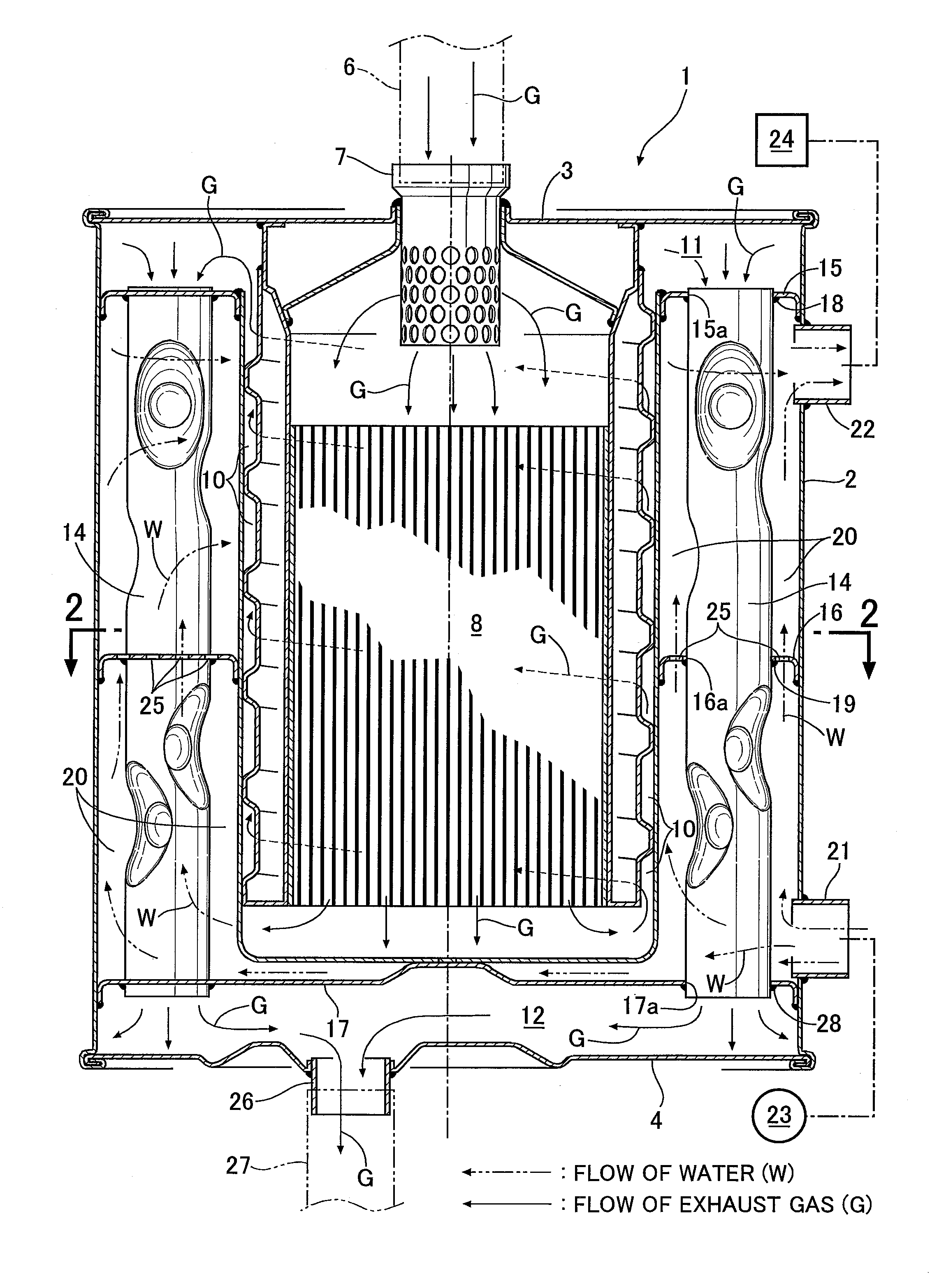
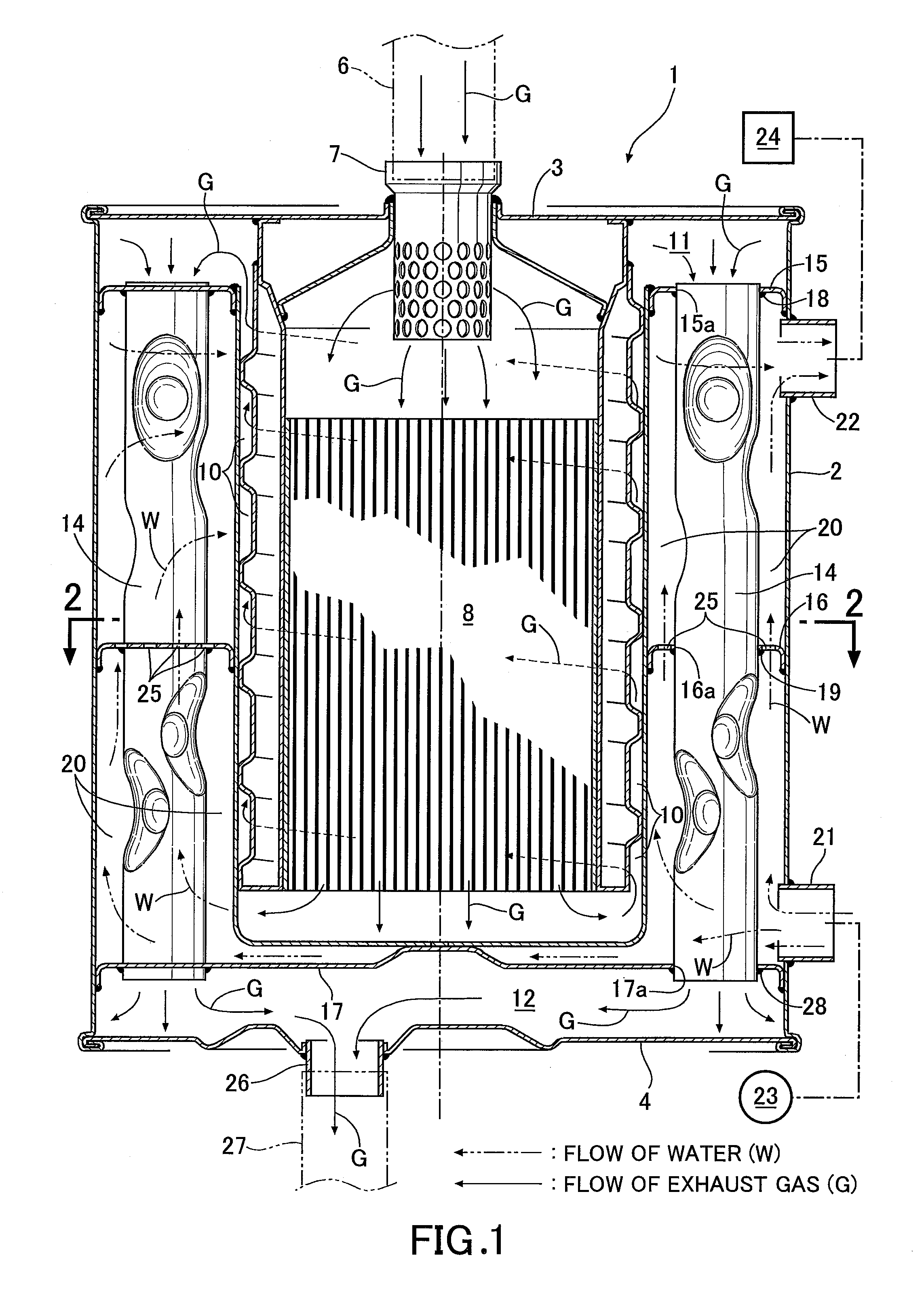
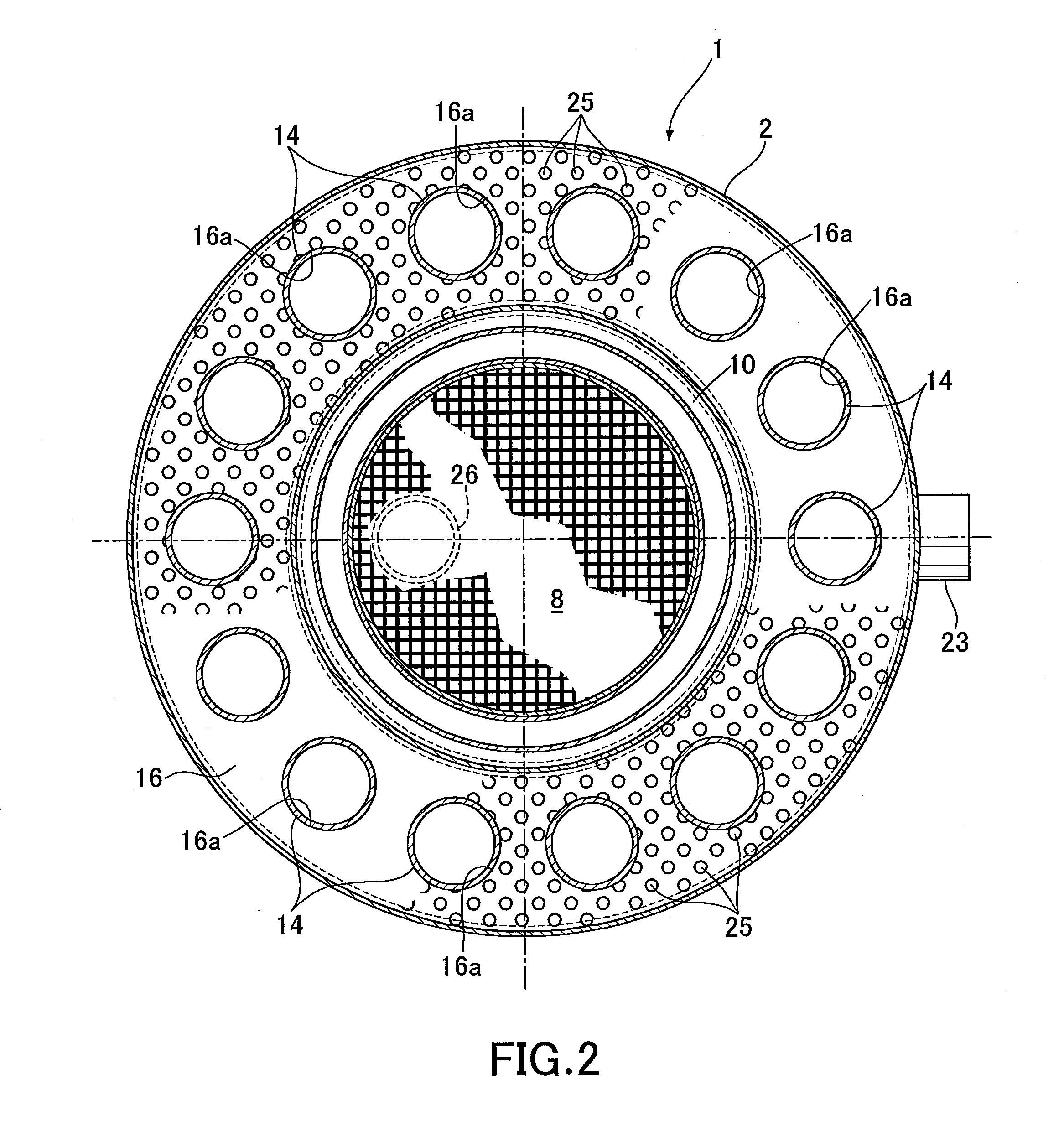
[0032]First, based on FIGS. 1 and 2, a heat exchanger 1 for gas cogenerator using the heat exchange tube 14 of the present invention will be described.

[0033]The heat exchanger 1 for cogenerator has an outer barrel 2, and upper and lower end plates 3 and 4 which are connected to opposite upper and lower ends of the outer barrel 2. An exhaust gas inlet pipe 7, to which an exhaust pipe 6 of a gas engine is connected, is connected to a center portion of the upper end plate 3. A catalyst converter 8 for purifying exhaust gas, which communicates with the exhaust gas inlet pipe 7 is placed at the center portion of the outer barrel 2.

[0034]A spiral exhaust gas flow path 10 which communicates with a lower end of the catalyst converter 8 is formed around the catalyst converter 8. The exhaust gas flow path 10 communicates with an annular upper exhaust gas chamber 11 which is formed at an upper portion of the insi...


PUM

PropertyMeasurementUnit
diameteraaaaaaaaaa
shapeaaaaaaaaaa
thicknessaaaaaaaaaa

Abstract

A heat exchange tube is constructed by forming, on a cylindrical tube peripheral wall, a plurality of projecting portions which project to an inside of the tube peripheral wall, and which are formed by pushing. The plurality of projecting portions are formed, respectively, into conical shapes across a tube axis, and are arranged along virtual spirals on the tube peripheral wall. Accordingly, it is possible to provide a heat exchange tube which facilitates formation of a plurality of projecting portions with the thickness hardly changed and without formation of protruded portions, and which is capable of contributing to enhancement of heat exchanging efficiency.

Description

TECHNICAL FIELD[0001]The application discloses an improvement of a heat exchange tube constructed by forming, on a cylindrical tube peripheral wall, a plurality of projecting portions which project to an inside of the cylindrical tube peripheral wall, and which are formed by pushing.BACKGROUND OF THE INVENTION[0002]A heat exchange tube is already known, as disclosed in, for example, Japanese Patent Application Laid-open No. 2004-85142. The heat exchange tube disclosed in Japanese Patent Application Laid-open No. 2004-85142 will be described based on FIGS. 7 to 9.[0003]There is a conventional heat exchange tube 014 in which a plurality of projecting portions 031 are arranged in a zigzag form along an axis of the tube as shown in FIG. 7. In this case, there are the projecting portions 031 as shown in FIG. 8 and FIG. 9. In FIG. 8, the projecting portion 031 is formed so that its ridge becomes linear, and a peripheral wall 030 of the portion other than the projecting portion 031 is not ...

Claims


Application Information

Patent Timeline
Patent Type & Authority Applications(United States)
IPC IPC(8): F28F1/10B23P15/26
CPCB21D28/28B21D31/06Y10T29/49391F28F1/42F28F1/426B21D53/06
Inventor HIROKAWA, ISAONAKAYAMA, TETSUAKIWATANABE, YASUYUKIKONDO, TOSHIHIRONAOI, ATSUMUUSHIYAMA, HIDEYUKI
Owner YUTAKA GIKEN CO LTD
Why Eureka
Try Eureka