Method and Apparatus for Ultrasonic Welding of Terminals

a terminal and ultrasonic welding technology, applied in the direction of auxillary welding devices, cell components, conductors, etc., can solve the problem that the debris created during ultrasonic welding can be injurious to the pouch

Inactive Publication Date: 2010-09-09
GM GLOBAL TECH OPERATIONS LLC
View PDF3 Cites 24 Cited by
  • Summary
  • Abstract
  • Description
  • Claims
  • Application Information

AI Technical Summary

Benefits of technology

[0004]The present invention provides a method and apparatus for welding of stacked battery terminals to an interconnect member and comprises generally juxtaposing two or more battery cell terminals to each other to create a terminal stack that includes an innermost terminal and an outermost terminal. The interconnect member is juxtaposed with the innermost terminal of the stack and an anvil is positioned against the interconnect member. An air stream is directed against the outermost terminal of the stack so that the air stream will compress the terminal stack and urge the innermost terminal into contact with the interconnect member. The sonotrode horn of an ultrasonic welder is then positioned in contact with the outermost terminal and is energized to vibrate the terminal stack and thereby make an ultrasonic weld between the stacked terminals of the terminal stack and the interconnect member. In addition, the air stream is directed at the terminal stack at a line of contact vertically below the sonotrode horn so that the air stream provides an air curtain to capture any debris that is created during the ultrasonic welding and prevent the debris from falling downwardly between the battery pouches. In addition, a suction is provided adjacent to the sonotrode horn to suction away the debris captured by the air curtain.

Problems solved by technology

In addition, there is a concern that any debris created during the ultrasonic welding can be injurious to the pouches if the debris is allowed to fall between the individual pouches.

Method used


Image

  • Method and Apparatus for Ultrasonic Welding of Terminals
  • Method and Apparatus for Ultrasonic Welding of Terminals
  • Method and Apparatus for Ultrasonic Welding of Terminals

Examples


Embodiment Construction

[0009]The following description of certain exemplary embodiments is exemplary in nature and is not intended to limit the invention, its application, or uses.

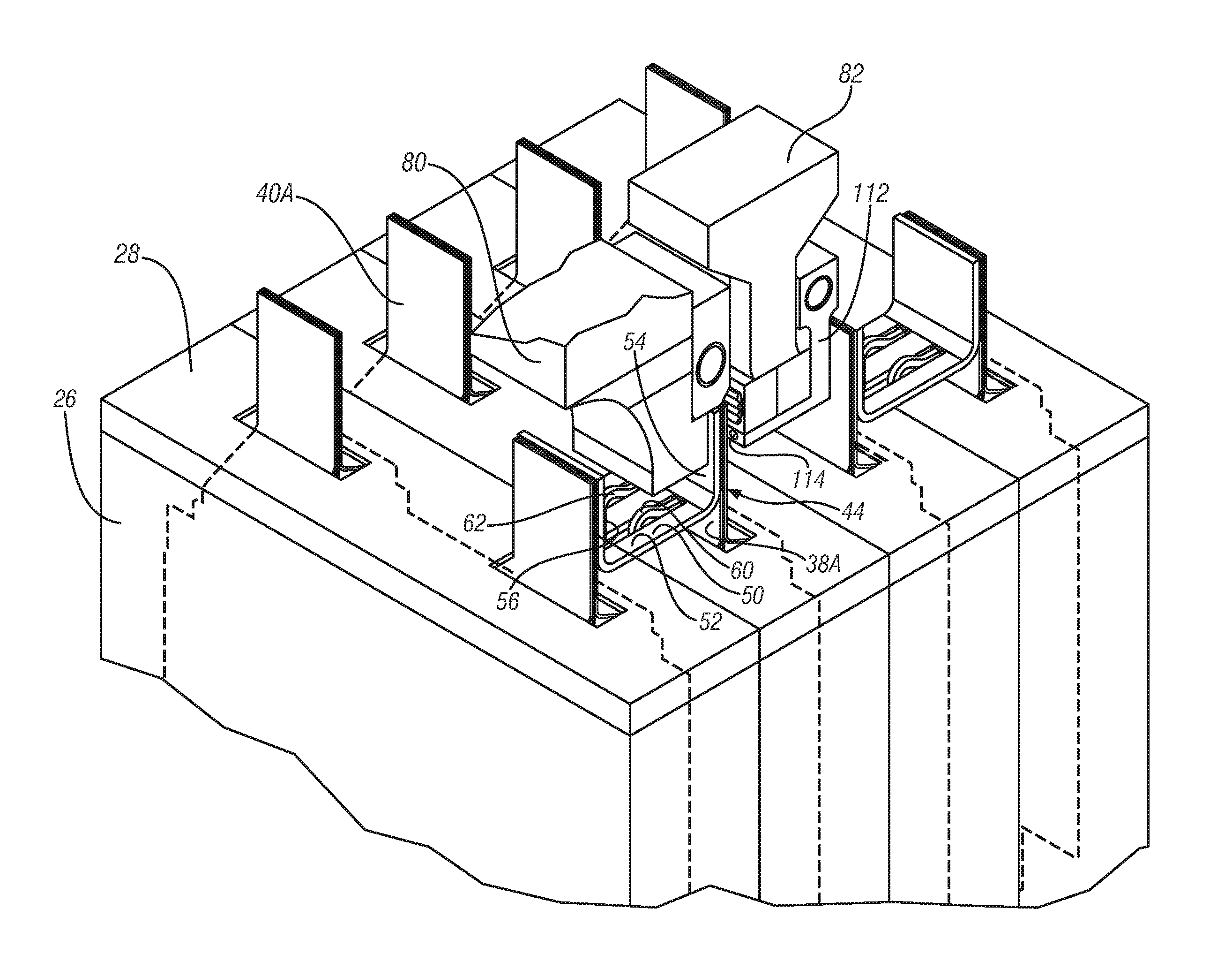
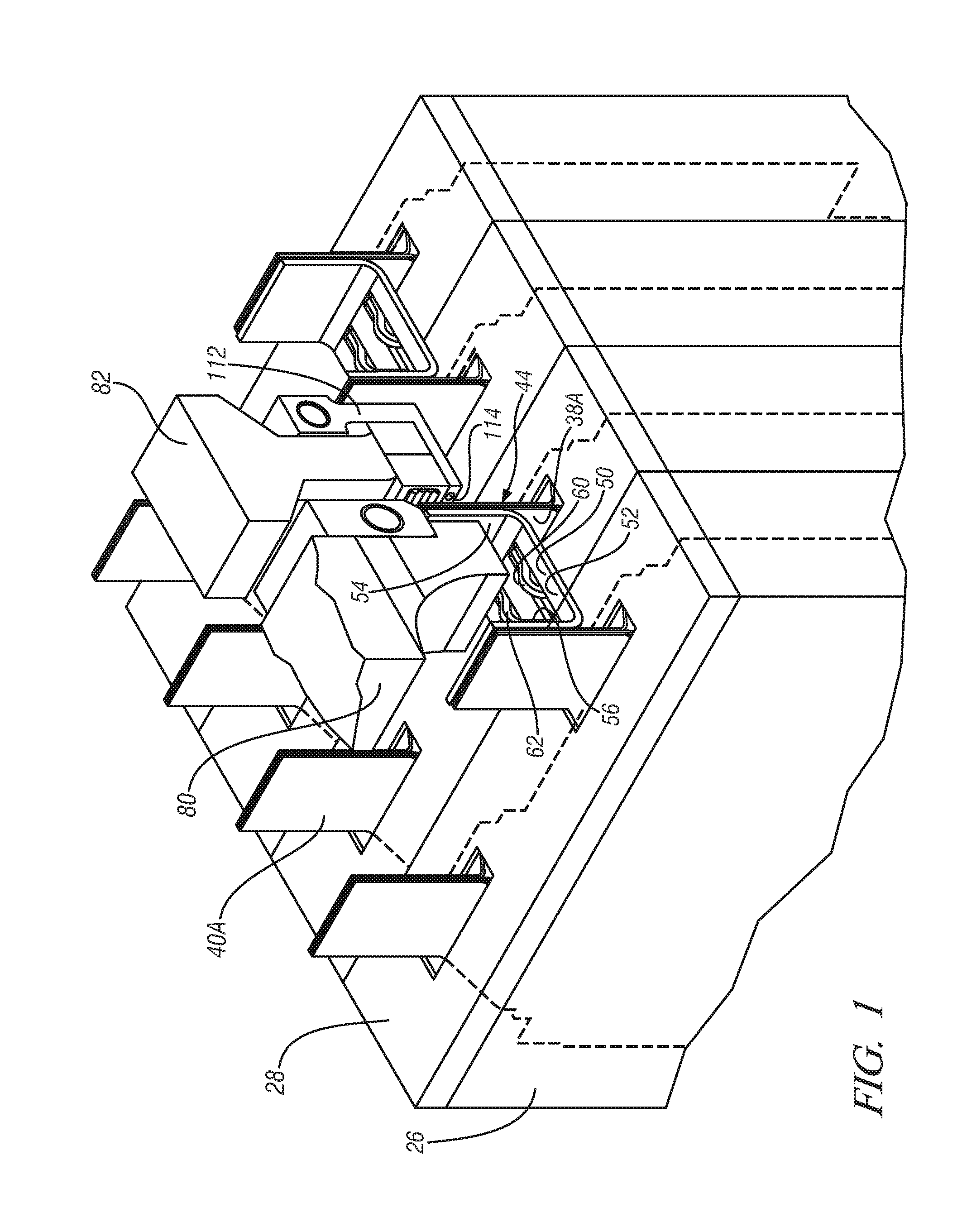
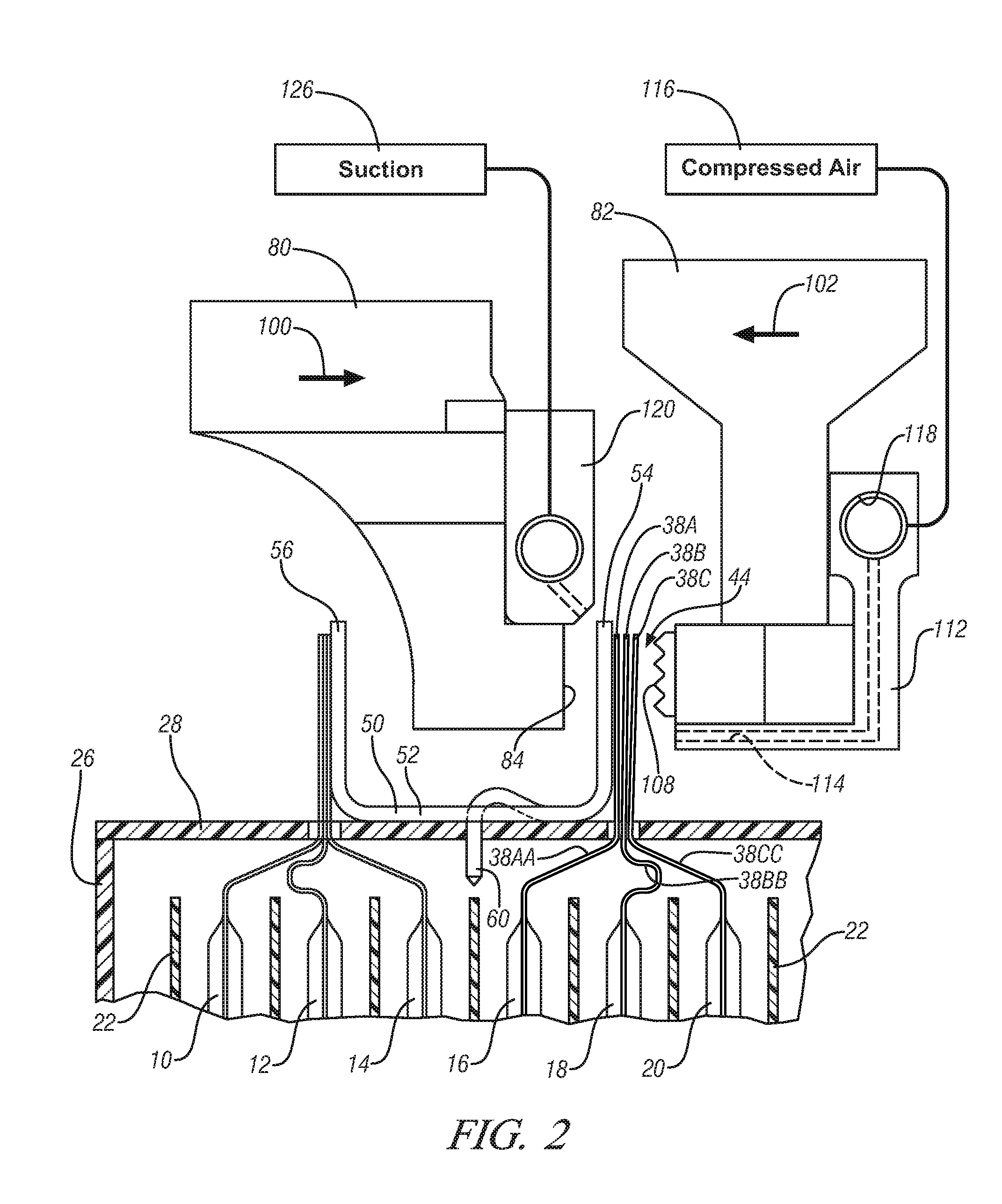
[0010]Referring to FIG. 2, it is seen that a battery pack or module, generally indicated at 8, has a plurality of individual battery cell pouches 10, 12, 14, 16, 18, and 20 are arranged side by side within a battery case 26 having a lid 28. Each of these battery cells pouches is a flexible bag-like container of lithium ion or other energy storage medium. The pouches are constructed of a relatively flexible material such as foil. The pouches are supported and separated in their side by side positions of FIG. 2 by support frames 22, as well insulators, heat exchangers and other structures that are not shown in the drawing. The battery cell pouch 16 is typical and includes a positive terminal 38A that extends out of the pouch 16. Also, as shown in FIG. 1, a negative terminal 40A extends out of the pouch 16. The positive terminal 38...


PUM

PropertyMeasurementUnit
thicknessaaaaaaaaaa
ultrasonic vibrationaaaaaaaaaa
suctionaaaaaaaaaa

Abstract

A method and apparatus for welding of battery terminals to an interconnect includes: juxtaposing two or more battery cell terminals to each other to create a terminal stack including an innermost terminal and an outermost terminal; juxtaposing a battery cell interconnect with the innermost terminal of the stack; positioning an anvil in contact with the interconnect; directing an air stream against the outermost terminal so that the air stream compresses the terminal stack and urges the innermost terminal into contact with the interconnect; positioning a sonotrode horn in contact with the outermost terminal; and energizing the sonotrode horn to vibrate the terminal stack and thereby make an ultrasonic weld between the stacked terminals of the terminal stack and the interconnect. The air stream is directed at the terminal below the sonotrode horn to capture any debris and a suction removes the debris.

Description

FIELD OF THE INVENTION[0001]The present invention relates to a method and apparatus for the ultrasonic welding together of a stack of battery terminals with an interconnect member.BACKGROUND OF THE INVENTION[0002]Rechargeable energy storage systems for motor vehicles are assembled by electrically connecting together a plurality of individual battery cells. For example, lithium-ion battery cells typically include a soft housing pouch having a positive terminal and a negative terminal extending outwardly from the pouch. These battery cells are positioned side by side in a battery case to bring the positive terminals together and the negative terminals together, thereby creating a stack of terminals to make a parallel electrical connection between the individual cells. These terminal stacks need to be attached to an interconnect member which will in turn connect to other such sub-assemblages of the battery cells.[0003]It would be desirable to use ultrasonic welding to attach the stack ...

Claims


Application Information

Patent Timeline
Patent Type & Authority Applications(United States)
IPC IPC(8): B23K20/10H01M50/503H01M50/516H01M50/528
CPCB23K20/10B23K2201/38Y10S228/901H01M2/266H01M2/206B23K2101/38Y02E60/10H01M50/516H01M50/503
Inventor SCHEUERMAN, ROBERT J.ROURKE, RICK F.
Owner GM GLOBAL TECH OPERATIONS LLC
Why Eureka
Try Eureka