Motor driving circuit and method for driving motor

Active Publication Date: 2010-09-09
ROHM CO LTD
View PDF7 Cites 35 Cited by
  • Summary
  • Abstract
  • Description
  • Claims
  • Application Information

AI Technical Summary

Benefits of technology

[0015]The present invention has been made in view of such a situation. Accordingly, it is an exemplary purpose of the present inve

Problems solved by technology

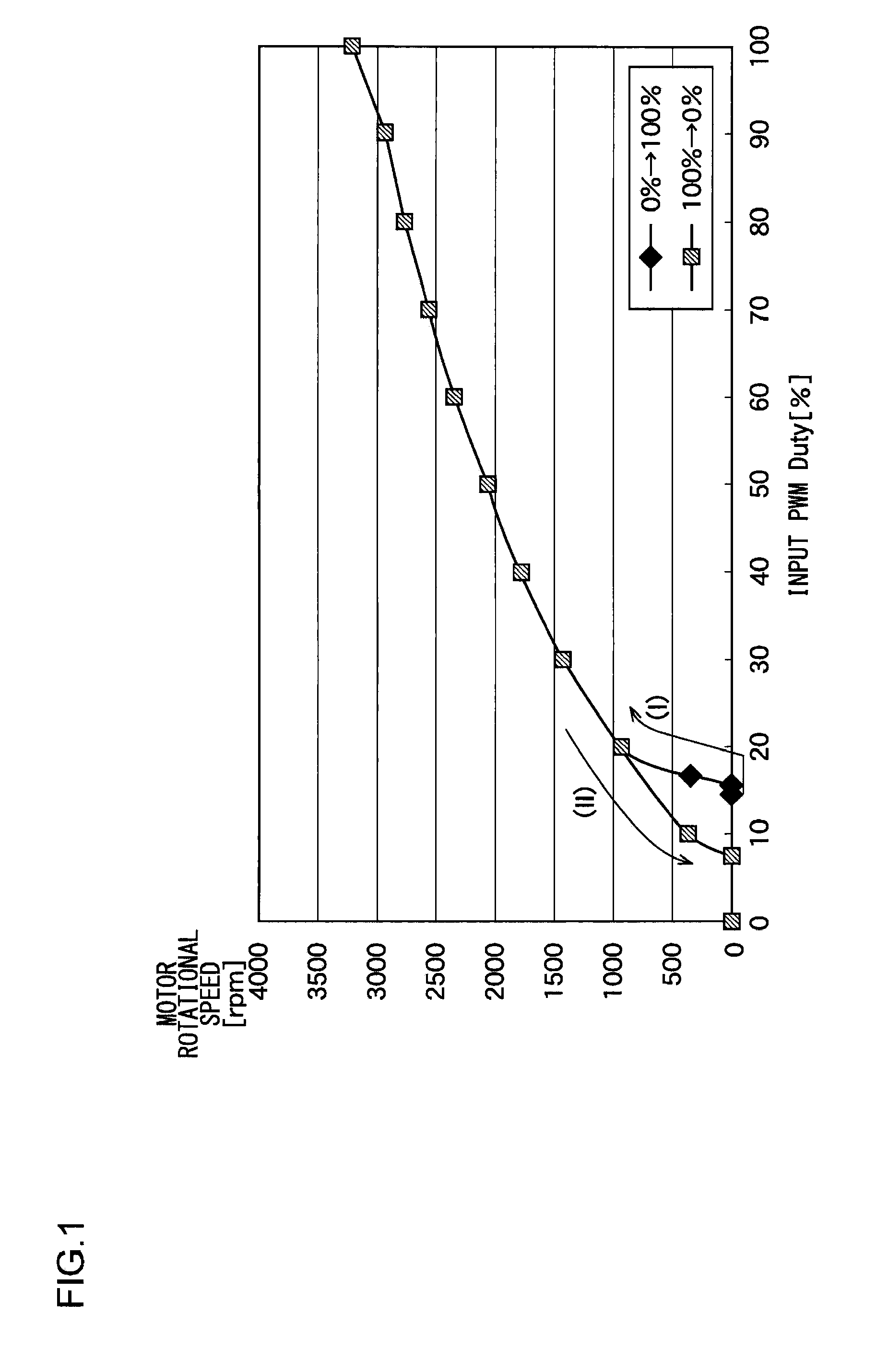
When the duty ratio is to be increased from 0% to 100% when the motor has stopped, a duty ratio in a range which is lower than a predetermined threshold value (e.g., 15%) is insufficient for the motor to start to rotate, leading to a situation in which the rotational speed of the motor remains zero.
However, as shown in FIG. 1, in some cases, such a low duty ratio results i

Method used


Image

  • Motor driving circuit and method for driving motor
  • Motor driving circuit and method for driving motor
  • Motor driving circuit and method for driving motor

Examples


Embodiment Construction

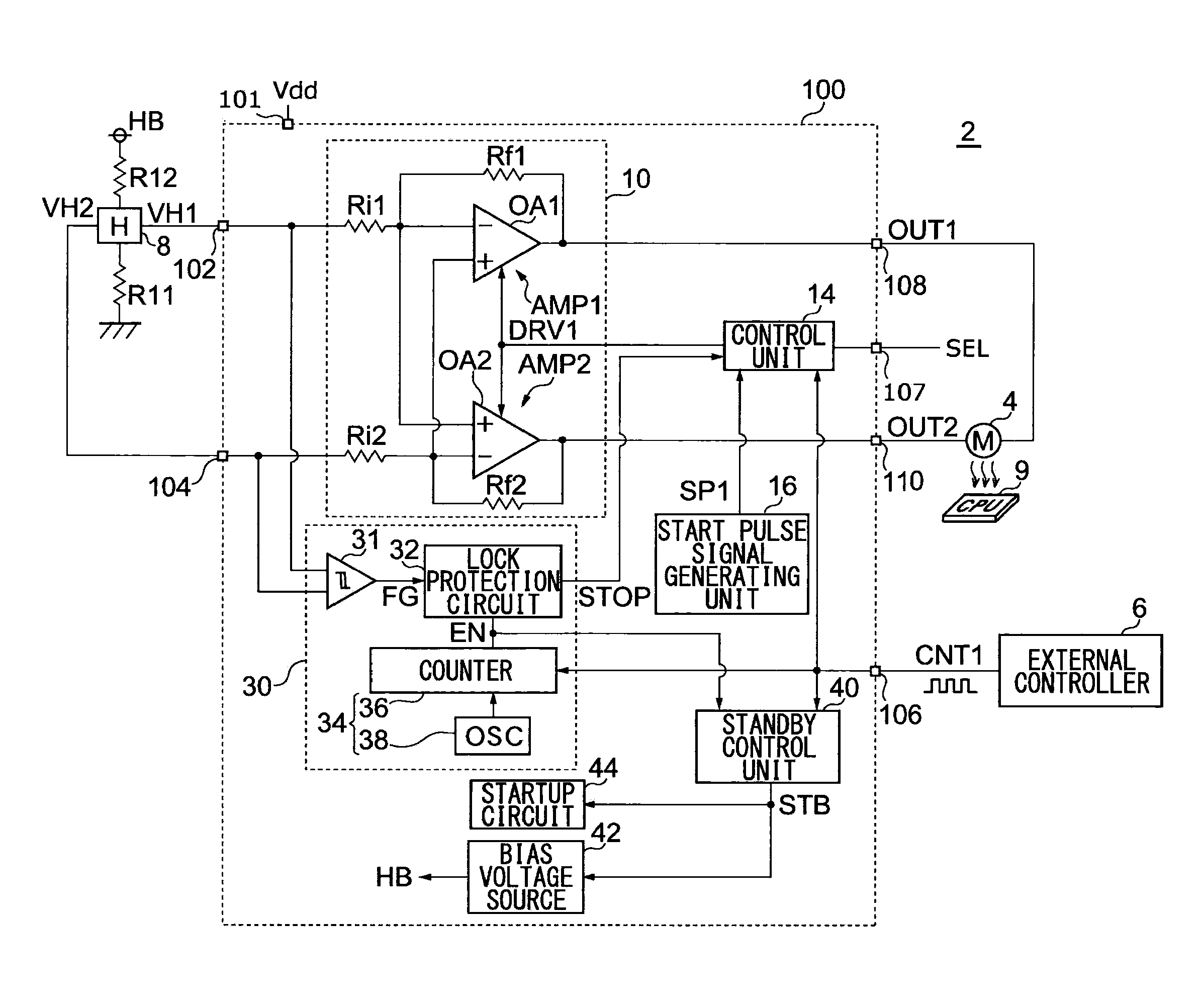
[0043]The invention will now be described based on preferred embodiments which do not intend to limit the scope of the present invention but exemplify the invention. All of the features and the combinations thereof described in the embodiment are not necessarily essential to the invention.

[0044]In the present specification, the state represented by the phrase “the member A is connected to the member B” includes a state in which the member A is indirectly connected to the member B via another member that does not affect the electric connection therebetween, in addition to a state in which the member A is physically and directly connected to the member B. In the same way, the state represented by the phrase “the member C is provided between the member A and the member B” includes a state in which the member A is indirectly connected to the member C, or the member B is indirectly connected to the member C via another member that does not affect the electric connection therebetween, in ...


PUM


Abstract

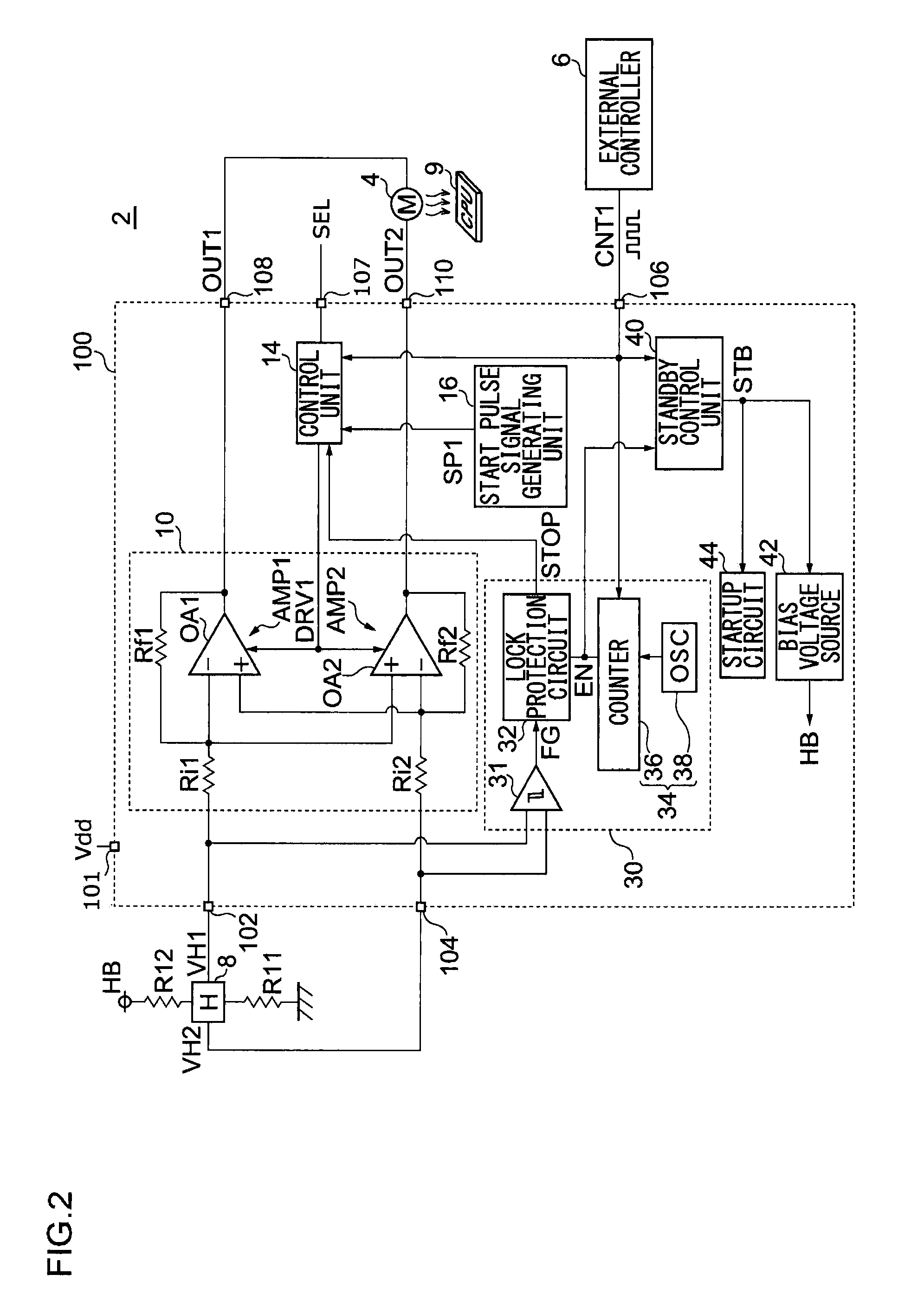
A motor driving circuit receives a control pulse signal pulse-width modulated according to a target rotational speed, and drives a fan motor. A start pulse signal generating unit generates a start pulse signal having a predetermined duty ratio. A driving unit drives the fan motor by pulse width modulation according to the driving pulse signal received from a control unit. When the duty ratio of the control pulse signal is switched from zero to a nonzero value when the fan motor is in the stopped state, the control unit commences the driving operation for the fan motor. The control unit outputs, as the driving pulse signal, the start pulse signal, in a predetermined start period Ts from the commencement of the driving operation. After the start period elapses, the control unit outputs the control pulse signal as the driving pulse signal.

Description

BACKGROUND OF THE INVENTION[0001]1. Field of the Invention[0002]The present invention relates to a motor driving technique using pulse width modulation (PWM), and particularly to a control technique for starting up the motor.[0003]2. Description of the Related Art[0004]In recent years, increase in the operation speed of personal computers and workstations has led to rapid increase in the operation speeds of computation LSIs (Large Scale Integrated Circuit) such as CPUs (Central Processing Unit), DSPs (Digital Signal Processor), etc. Such LSIs have a problem in that an increase in the operation speed, i.e., an increase in clock frequency involves an increase in heat generation. The heat generation of the LSI leads to thermal runaway of the LSI itself, or affects its peripheral circuits, which becomes a problem. Accordingly, such a situation requires a suitable thermal cooling operation for the LSI, as a crucial technique.[0005]Examples of techniques for cooling an LSI includes an air...

Claims


Application Information

Patent Timeline
IPC IPC(8): H02P1/04H02P1/18H02P7/288H02P7/29
CPCH02P7/29H02P1/18
Inventor MISHIMA, TOMOFUMI
Owner ROHM CO LTD
Why Eureka
Try Eureka